
Producing yarn

a technology of yarn and process, applied in the direction of fiber mixing, mechanical equipment, transportation and packaging, etc., can solve the problems of elastic hysteresis, wear on the belt, and failure mode, so as to reduce the beneficial properties of heat resistant materials, improve the distribution of heat resistant fibres, and reduce the benefits of invention.

Active Publication Date: 2011-04-28
HEATHCOAT FABRICS LTD
View PDF5 Cites 10 Cited by
  • Summary
  • Abstract
  • Description
  • Claims
  • Application Information

AI Technical Summary

Benefits of technology

[0015]A great advantage of the present invention is that texturised thermoplastic polymers can be used in combination with heat resistant materials but, after activation, the heat resistant material will not be forced out of the bundle thereby avoiding formation of loops or loose fibres. Because the process involves the preparation of a mixed bundle from a sliver comprising fibres of the heat resistant material (preferably non-thermoplastic polymer such as aramid), after activation the fibres of the heat resistant material tend to overlap rather than being forced out of the yarn. This means that the beneficial properties deriving from the heat resistant material are retained in the yarn even after activation.
[0016]Activation is a process involving scouring (i.e. washing in water) and drying and results in bulking of the thermoplastic polymer, especially a texturised thermoplastic polymer. Preferably, the process further comprises at least one activation step.
[0017]The thermoplastic polymer may be selected from polyamide, polyester, PBT, poly ether either ketone, poly ether imide or polyolefin (e.g. polyethylene or polypropylene). Of these thermoplastic polymers the currently preferred thermoplastic polymer is polyamide and in particular nylon (for example PA66, PA46 or PA6).
[0018]Usually, the bundle of filaments of thermoplastic polymer will be contacted with the sliver after carding and / or combining and during a drawing step (usually on the drawing frame).
[0019]After the mixed bundle has been formed, preferably it undergoes at least one further step to produce the finished yarn. This is to improve the distribution of the heat resistant fibre in the final yarn.
[0020]In the process of the invention, the mixed bundle preferably comprises the fibres of the heat resistant material in an amount of between 5 and 75% by weight. Less than about 5% by weight will result in less of the beneficial properties of the heat resistant material being apparent in the bundle or the mixed yarn after spinning. At more than about 75% by weight, the benefits of the invention are likewise reduced.

Problems solved by technology

Distortion of the teeth during use leads to wear on the belt and is a mode of failure.
Additionally, the distortion of the teeth leads to elastic hysteresis, which in turn leads to the build up of heat.
Unfortunately, aramid filaments alone have a very high modulus and so are not elastic enough to enable good forming on the mould or be acceptable in use as a transmission belt.
A combination of aramid with nylon and elastomer has been attempted, but can introduce further problems because elastomers can degrade leaving voids in the transmission belt that possibly accelerate wear and reduce life.
Use of texturised nylon and aramid filament leads to problems on activation (using methods such as scouring) because, after the yarn bulks, the aramid filament is forced out of the bundle causing loops.
Loops cause disadvantages including reduced abrasion resistance and hence reduced durability, reduced consistency of the final product, reduction of the dynamic performance of the fabric especially in terms of stretch characteristics and a reduced or inconsistent adhesion performance.

Method used


Image

  • Producing yarn
  • Producing yarn
  • Producing yarn

Examples


Embodiment Construction

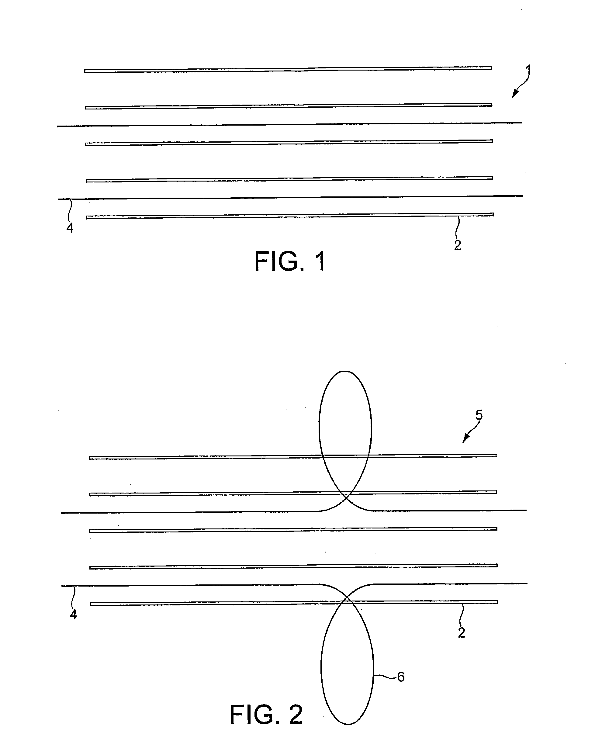
[0033]FIG. 1 illustrates a comparative yarn 1, which consists of thermoplastic filaments 2 of Nylon 66, and heat resistant material filaments, of para aramid 4. Before activation the filaments of thermoplastic polymer 2 and heat resistant material 4 are well mixed in the yarn.

[0034]FIG. 2 illustrates the comparative yarn 5 after activation (scouring in water and drying). The activation process shrinks and bulks the bundle of thermoplastic polymer filaments 2. However, the heat resistant material filaments 4 do not act in the same way as the thermoplastic filaments 2. Consequently, the heat resistant filaments 4 are forced out of the mixed yarn forming loops 6. Loops 6 cause disadvantages including reduced abrasion resistance and hence reduced durability, reduced consistency of the final product, reduction of the dynamic performance of the fabric especially in terms of stretch characteristics and a reduced or inconsistent adhesion performance.

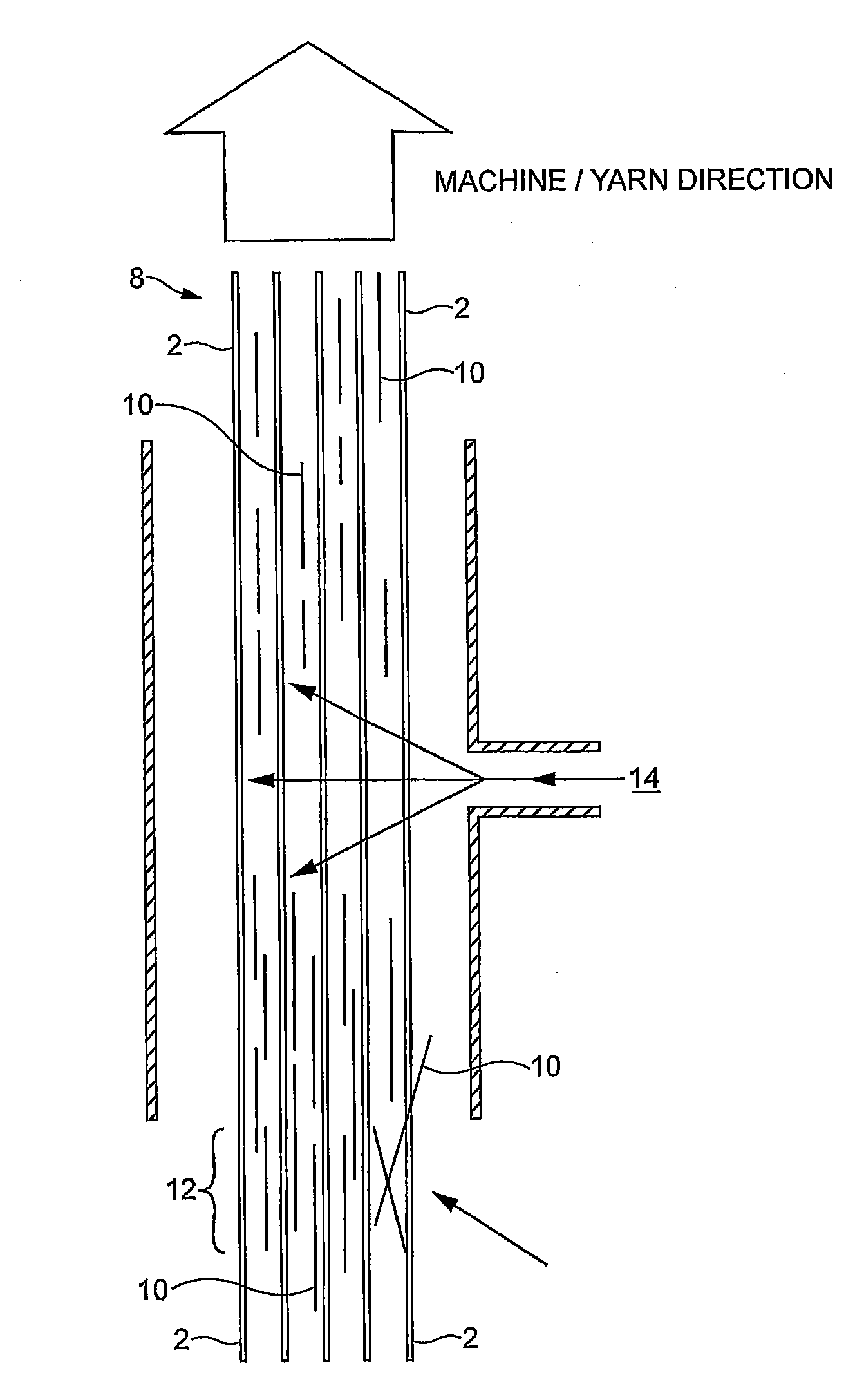
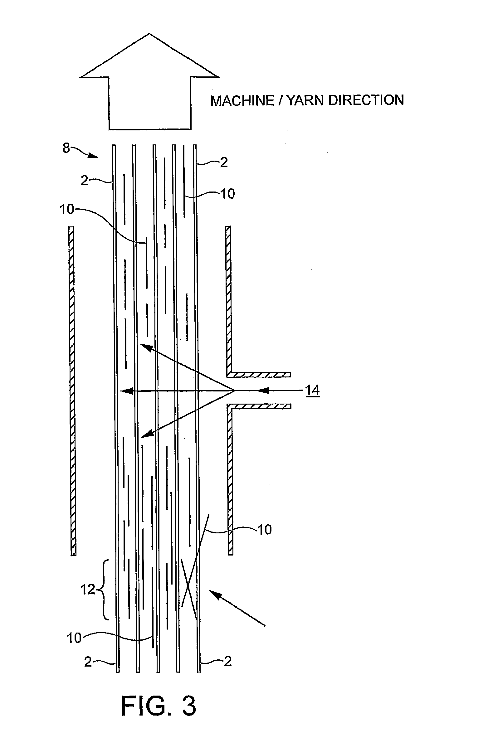
[0035]FIG. 3 illustrates the process acco...


PUM

PropertyMeasurementUnit
lengthaaaaaaaaaa
lengthaaaaaaaaaa
lengthaaaaaaaaaa

Abstract

A process for the production of a yarn is disclosed, the process comprising providing a bundle comprising continuous filaments of a thermoplastic polymer, contacting the bundle with a sliver comprising fibres of a heat resistant material to form a mixed bundle, and applying a gas jet to the mixed bundle to distribute the fibres of the heat resistant material in the bundle. Also disclosed are yarns comprising filaments of a thermoplastic polymer and fibres of a heat resistant material, wherein the fibres are distributed between and among the filaments. Preferably, the heat resistant material is a non-thermoplastic polymer, especially an aramid. Yarns according to the invention find use in technical fabrics especially transmission belts.

Description

[0001]This application is a continuation of International Application No. PCT / GB2009 / 050391, filed Apr. 20, 2009, which is incorporated herein by reference.BACKGROUND OF THE INVENTION[0002]The present invention relates to processes for producing yarn, to yarns produced by the processes, to fabrics comprising the yarn and to transmission belts comprising such fabrics.[0003]Existing transmission or timing belts, when used in engines or the like, are designed with teeth which mesh with appropriate pulleys to provide synchronised power transmission. The transmission belts are formed by pressing a suitable resilient fabric over a mould to mould the teeth and impregnating the fabric with suitable elastomer. Distortion of the teeth during use leads to wear on the belt and is a mode of failure. Additionally, the distortion of the teeth leads to elastic hysteresis, which in turn leads to the build up of heat.[0004]Nylon has usually been chosen as a fabric forming the surface of the belt whic...

Claims


Application Information

Patent Timeline
Patent Type & Authority Applications(United States)
IPC IPC(8): F16G1/04D01G13/00B32B5/02E04B1/74
CPCD02G3/22D02G3/402D02G3/443D02G3/447Y10T428/2931F16G1/10Y10T428/2918D01F8/12F16G1/04D02J1/18Y10T428/249921
Inventor CRANE, RICHARD
Owner HEATHCOAT FABRICS LTD
Learn More