

Preparatory Reamers For Orthopedic Implants
- Summary
- Abstract
- Description
- Claims
- Application Information
AI Technical Summary
Benefits of technology
Problems solved by technology
Method used
Image

Examples
Embodiment Construction
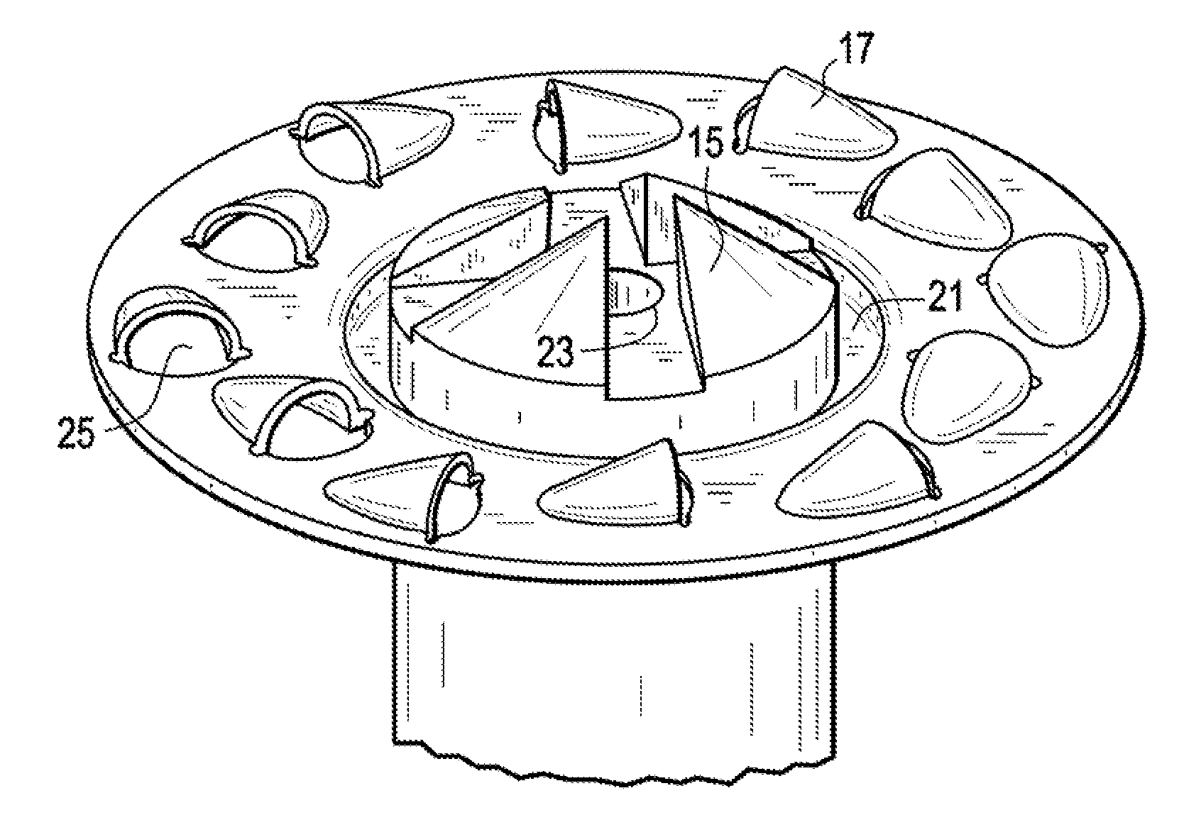
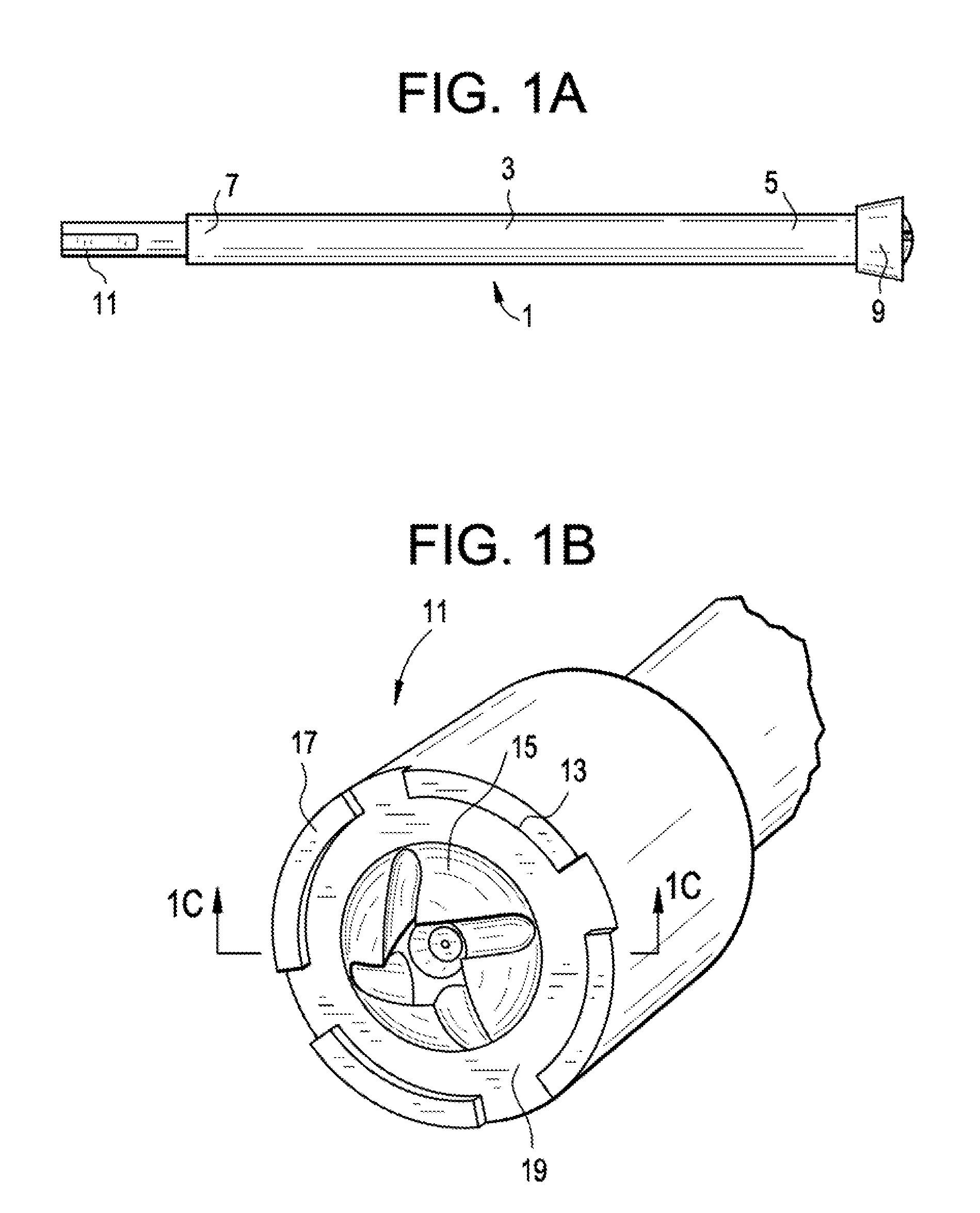
[0037]Now referring to FIGS. 1a and 1b, there is provided a drill bit 1 for preparatory reaming of a spinal facet surface, comprising:
[0038]a) a shaft 3 having a proximal end portion 5 and a distal end portion 7,
[0039]b) a drill attachment feature 9 extending from the proximal end portion of the shaft, and
[0040]c) a cutting bit 11 extending from the distal end portion of the shaft,
wherein the cutting bit has a distal face 13 comprising:
[0041]i) a plurality of circumferentially-disposed inner cutting surfaces 15,
[0042]ii) a plurality of circumferentially-disposed outer cutting surfaces 17, and
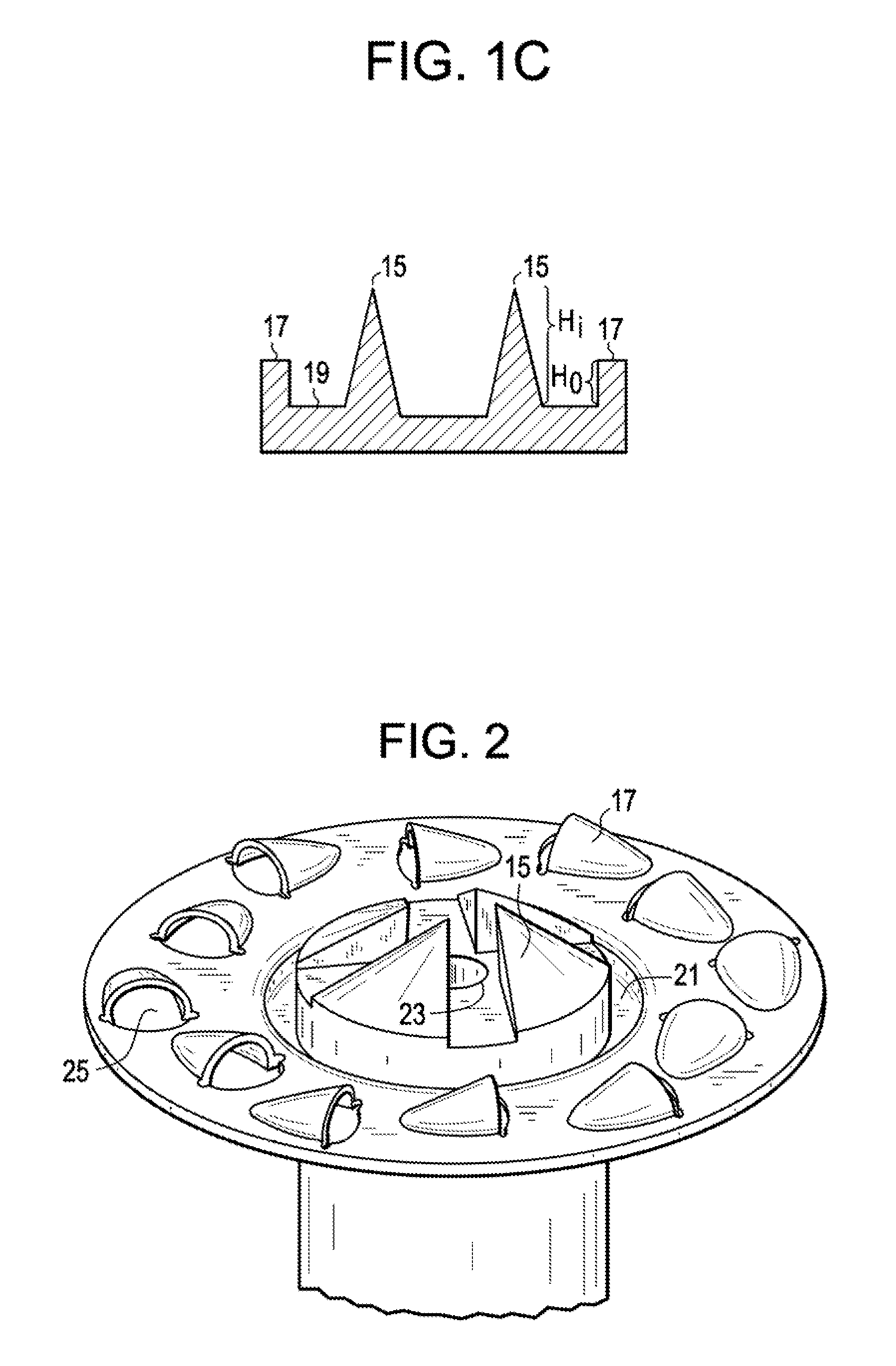
[0043]iii) a circumferential flat 19 located radially outside the inner cutting surfaces.
[0044]Now referring to FIG. 1c, the inner cutting surfaces 15 have a height Hi and the outer cutting surfaces 17 have a height Ho, and the height Hi of the inner cutting surfaces is greater than the height Ho of the outer cutting surfaces. In this embodiment, the greater height of the inner cutting surface a...
PUM
 Abstract
Description
Claims
Application Information