Optical Rectification Device and Method of Making Same

Inactive Publication Date: 2011-05-05
RICE UNIV
View PDF5 Cites 14 Cited by
  • Summary
  • Abstract
  • Description
  • Claims
  • Application Information

AI Technical Summary

Problems solved by technology

Due to rapidly rising fossil fuel costs, energy security issues and solar energy harvesting technologies have become increasingly important due to concurrent concerns with increasing fossil fuel costs, energy security and anthropogenic global warming.

Method used


Image

  • Optical Rectification Device and Method of Making Same
  • Optical Rectification Device and Method of Making Same
  • Optical Rectification Device and Method of Making Same

Examples


example 1

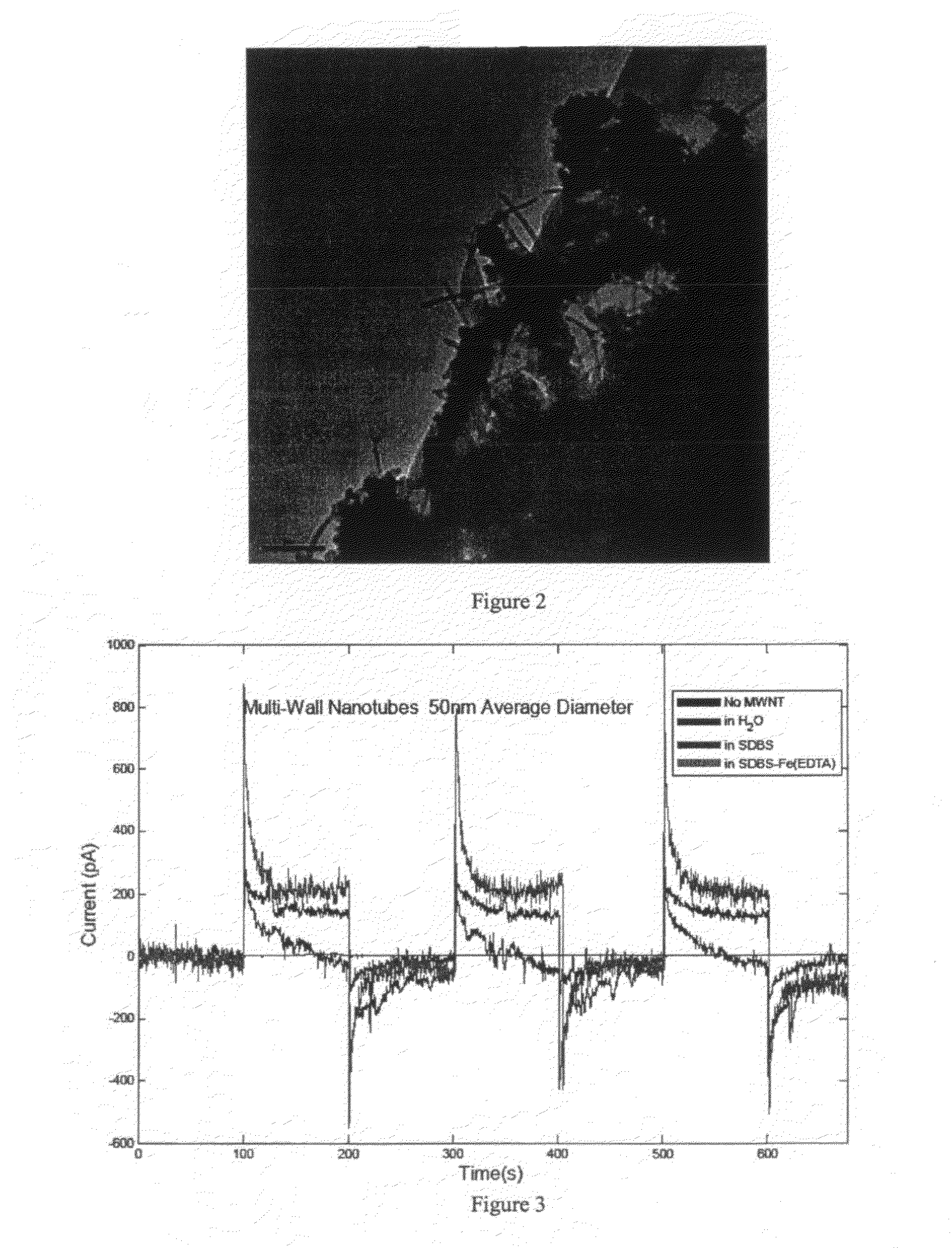
[0067]This example illustrates rectification using a surfactant.

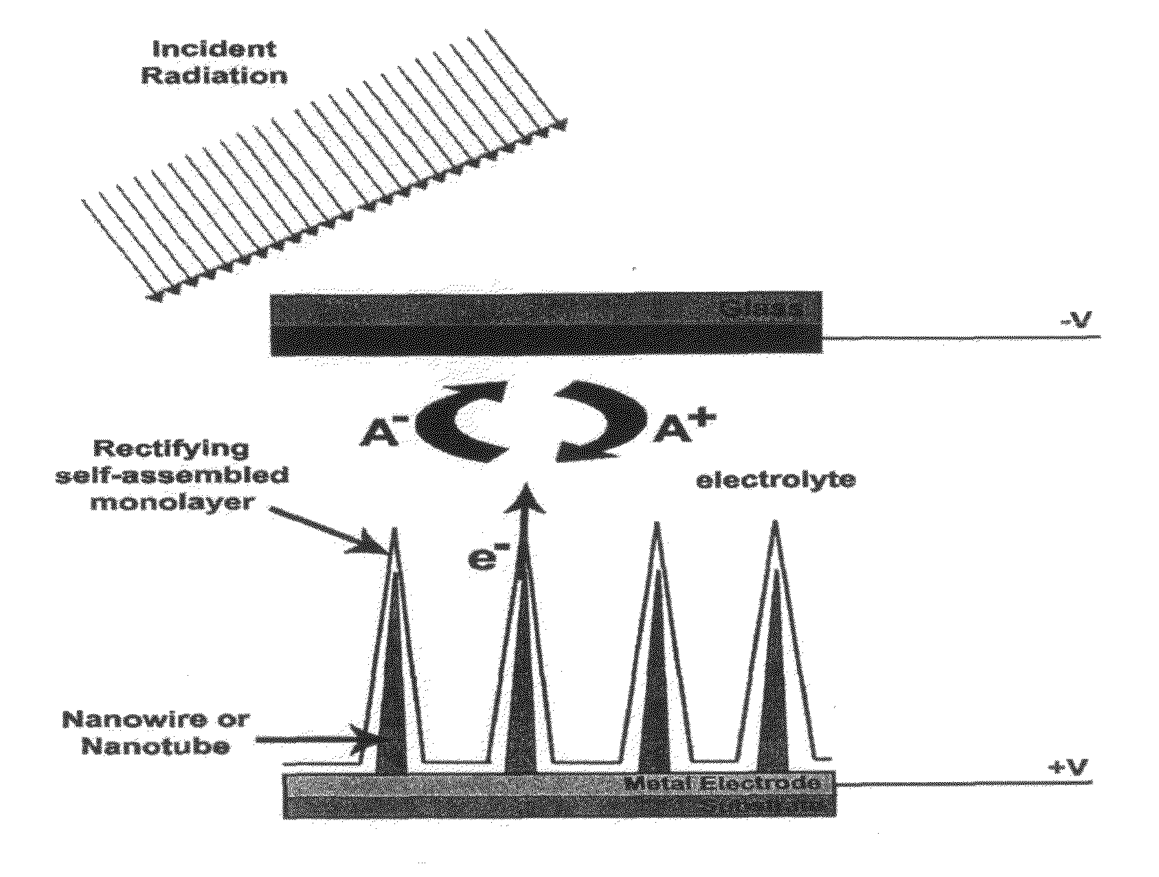
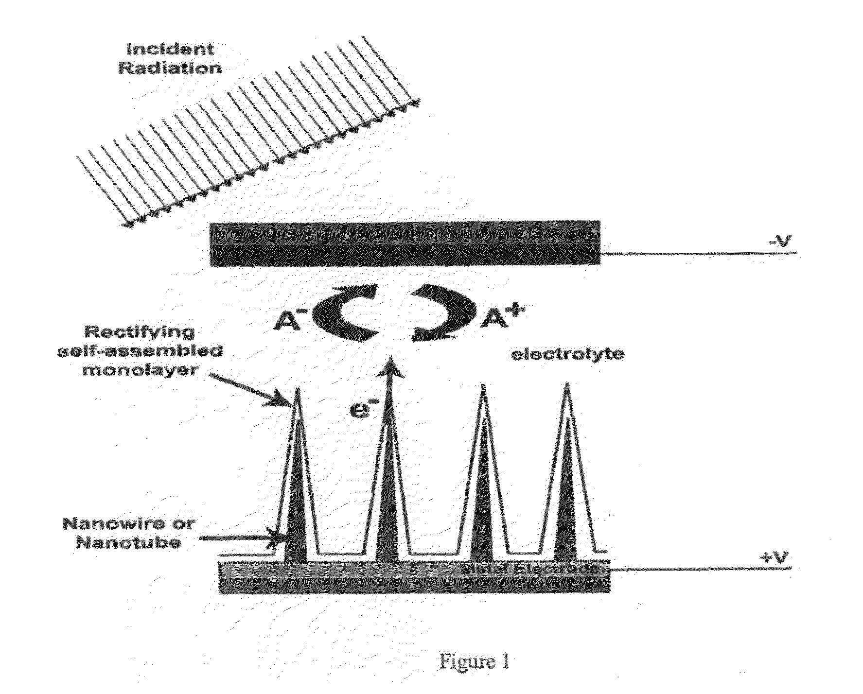
[0068]The present inventors obtained small DC photocurrents from carbon nanotube electrodes in aqueous electrolytes, demonstrating conversion of light to electricity. The demonstration device described in this example was produced by coating carbon tape (conductive adhesive) with carbon nanotubes; this was affixed to a conductive substrate which served as an electrode. This was immersed in a aqueous electrolyte solution of SDBS (sodium dodecylbenzene sulfonate) and Fe(EDTA)2. SDBS is a common detergent. A gold wire or similar was immersed into the electrolyte, but not directly in contact with the carbon tape or its supporting electrode. Upon irradiation with light, electrons were emitted from the nanotubes into the solution. Electrons were carried to the gold wire, which charged negative; the substrate in contact with the nanotubes charges positive.

[0069]In particular, the present inventors fabricated a photocathode by ...

example 2

A Prophetic Example

[0073]This example illustrates generation of a voltage by a nanoscale antenna.

[0074]The present inventors model the voltage generated at the tip of a nanowire antenna. The present inventors assume that initially the amount of energy stored in the polarized wire is equal to the energy in the incoming photon hv. It is known that the polarization of a conducting wire in an axial electric field is P=γ↑E|L3 / Λ, where the geometrical factor Λ=[24 ln(4L / d)−7] and E is the applied field; L and d are the length and diameter of the rod, respectively. The energy stored is given by the product of electric field and the polarization: D=P E, while the apparent voltage (relative to immediate surroundings) at the tip will be E L / 2. Equating the D is with hv, it is possible to compute the field that would have generated such a dipole, and thus the impressed voltage at the tip of the wire. FIG. 4 shows the results. For example, the present inventors predict that a 10 nm×150 nm anten...

example 3

Another Prophetic Example

[0075]This example illustrates rectification by an dipole bilayer.

[0076]The present inventors model the potential well created by a charged nanotube with a surfactant micelle. The present inventors reasonably assume a surfactant structure as shown in FIG. 5 along with a surfactant anionic charge density of 0.1 C / m2 and a nominal surfactant dipole moment of 20 Debye. It is possible to compute the size of the offset from the bath using Gauss's law to determine the radial electric field at various radii based upon the surface area of the cylindrical surface (or hemi-spherical at the ends) and the enclosed charge.

[0077]From this, it is possible to see that the region between the ionic component layers has a strong electric field. Upon integrating this field, it is possible determine the size of the voltage offset (the depth of the potential well) caused by the ordered dipole SAM. Results were obtained also for cylindrical and spherical symmetry, corresponding to...


PUM


Abstract

A general approach is provided for producing devices that absorb optical photons (visible to near IR) and performs charge separation with a useful voltage between holes and electrons. These holes and electrons may be collected in electrodes for performing useful work outside the device. The described technology is generally based upon rectification of plasmons (collective electric excitations) generated by absorbing light with tuned metallic antennas. According to some embodiments, the present invention provides a spatial array of nanoscale conductors forming an optical rectenna that responds to an incident light source and generates a current offset that may be rectified by a rectification-inducing material. The present inventors foresee an extensive use of these optical rectennas as photovoltaic devices, as well as a wide interest in diverse fundamental research and applied technologies.

Description

CROSS-REFERENCE TO RELATED APPLICATION[0001]This application claims priority to and benefit of U.S. Provisional Application Ser. No. 60 / 955,816, filed on Aug. 14, 2007, entitled: “Optical Rectification Device and Method of Making Same”, by inventors Schmidt, et al. [Attorney Docket No. 11321-P160V1], hereby incorporated herein by reference.GOVERNMENT SPONSORSHIP[0002]Not applicable.FIELD OF THE INVENTION[0003]The present inventions relates to photovoltaic devices based on optical rectification devices, and their application for photovoltaics.BACKGROUND OF INVENTION[0004]Due to rapidly rising fossil fuel costs, energy security issues and solar energy harvesting technologies have become increasingly important due to concurrent concerns with increasing fossil fuel costs, energy security and anthropogenic global warming. Renewable energy sources are a topic of high interest. Solar energy is the most abundant renewable source of energy, with an estimated flux of 165,000 terawatts (TW) hi...

Claims


Application Information

Patent Timeline
Patent Type & Authority Applications(United States)
IPC IPC(8): H01L31/06
CPCY02E10/542H01G9/2045H01L31/1085Y02P70/50
Inventor SCHMIDT, HOWARD K.DUQUE, JUAN
Owner RICE UNIV
Why Eureka
Try Eureka