Debugging Device

a technology of debugging device and device body, which is applied in the field of debugging tools, can solve the problems that the breakpoint may not stop all peripherals, and achieve the effects of reliable results, simple and accurate measurement, and reduced time involved in debugging a system

Inactive Publication Date: 2011-05-05
UNIVERSITY OF LEICESTER
View PDF5 Cites 11 Cited by
  • Summary
  • Abstract
  • Description
  • Claims
  • Application Information

AI Technical Summary

Benefits of technology

[0025]An advantage of the present invention is that time intervals between pre-determined events can be measured simply and accurately, with minimal interference to the normal operation of the system. In addition, due to the device analysing and modifying the system code, the time involved in debugging a system can be greatly reduced along with the risk of human errors. Furthermore, the present invention can be used to perform repeatable measurements with reliable results.
[0026]The debugging tool of the present invention may be configured for use in debugging traditional general-purpose processors running time-triggered software, or dedicated time-triggered processors. The tool may also be configured for use with a system-on-chip or a system simulator.
[0027]In the case where the tool is used with a dedicated time-triggered processor, the processor may be configured such that when a breakpoint is encountered, a system co-processor is triggered to signal external debug circuitry to broadcast a pause request to the instruction processing unit (IPU) and to all peripherals. This request may cause the IPU and peripherals to stop all processing by de-asserting the clock enables in their respective flip-flop circuitry.
[0028]The means for measuring the time between pre-determined breakpoints may comprise a mechanism for using a timer provided for the scheduler. In this case, the timer may overrun if, say, the task period is long. Accordingly, the means for measuring the time between pre-determined breakpoints may comprise a separate ‘debug’ timer with a pre-determined overrun time to permit the intended measurement periods.
[0029]In either of the above cases, the value of the timer employed is noted when a first breakpoint is encountered, then the timer is resumed and its value noted again when a subsequent breakpoint is encountered, thereby to measure or calculate the elapsed time.
[0030]The task details may comprise the task name or identifier, the location of each task in memory and the number of tasks.

Problems solved by technology

Such breakpoints may not stop all peripherals.

Method used


Image

  • Debugging Device
  • Debugging Device
  • Debugging Device

Examples


Embodiment Construction

[0044]The present invention provides a simple mechanism that can be used for the accurate collection of relevant debug information from TT embedded systems.

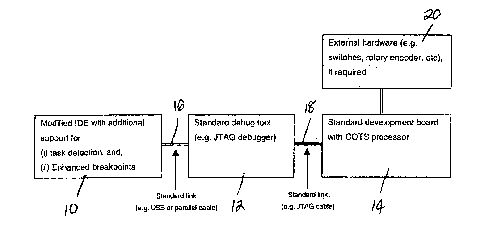
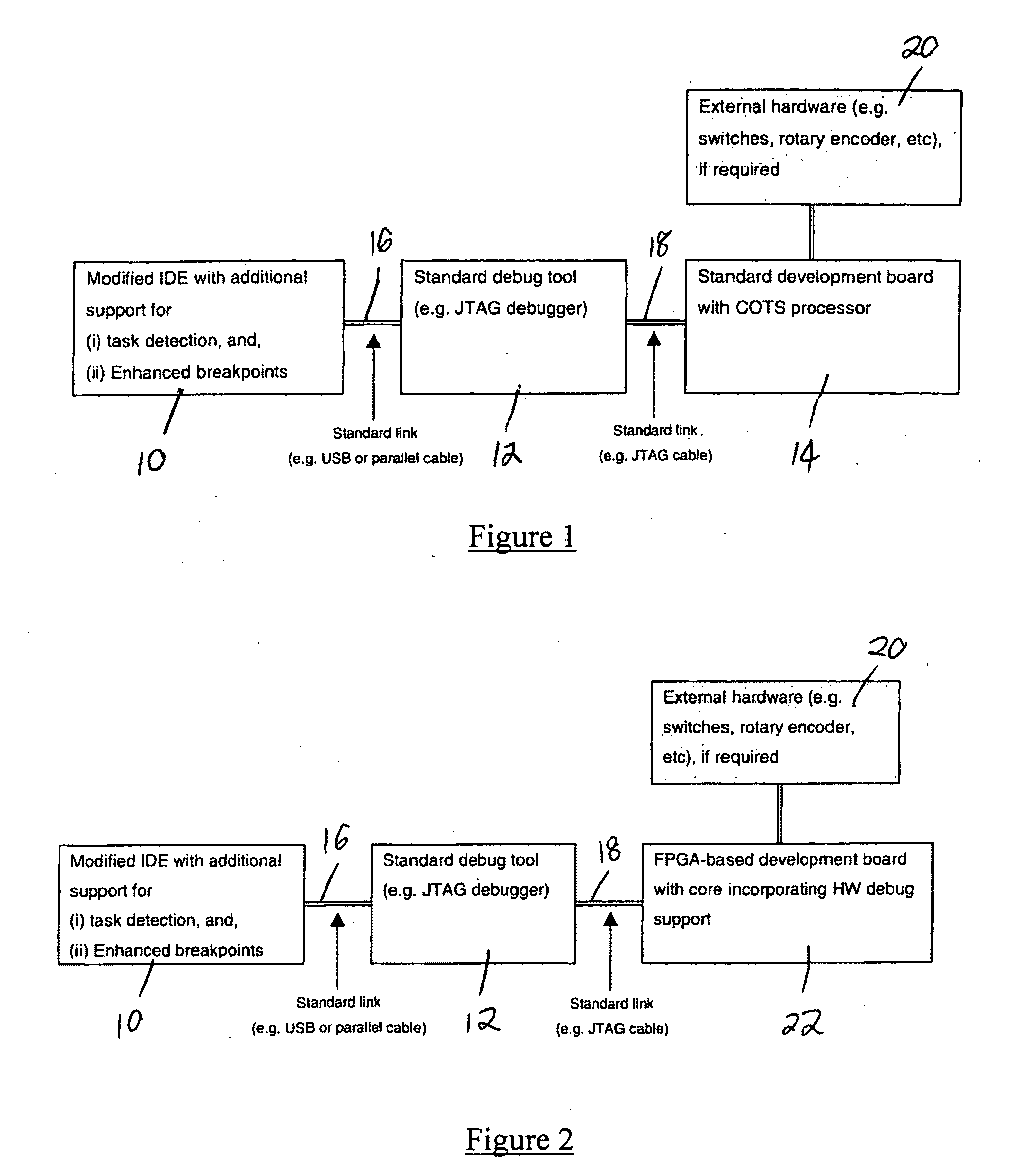
[0045]In an embodiment of the present invention, an Integrated Development Environment (IDE) 10 is employed on a general-purpose PC. In this embodiment, a standard (‘Eclipse’) IDE framework was used which was coupled to a C / C++ Development Tool (CDT). The IDE 10 was modified to include support for task detection and enhanced breakpoints. Accordingly, the modified IDE 10 constitutes a debugging tool according to an embodiment of the present invention.

[0046]In addition, a suitable piece of debug hardware 12 is employed, for example using the JTAG standard, to link the PC to the processor to be tested. In two particular test set-ups described below, a Wiggler™ and an ARM-USB-OCD device are used, respectively, as the debug hardware 12.

[0047]In one embodiment, a general-purpose (COTS) processor 14 configured to run 3 periodic tasks (A...


PUM


Abstract

A debugging tool for a time-triggered system comprises means for interrogating the system code to determine task details; means for modifying the system code to include breakpoints, the position of the breakpoints being determined by the task details; means for executing the modified system code; means for measuring the time between pre-determined ones of said breakpoints; and means for reporting the timing results to a user.

Description

FIELD OF THE INVENTION[0001]This invention relates to a debugging tool. Particularly, but not exclusively, the invention relates to a debugging tool that is suitable for use in the development of time-triggered embedded systems.BACKGROUND TO THE INVENTION[0002]Embedded processors are ubiquitous: they form a core component of a vast range of everyday items (cars, aircraft, medical equipment, factory systems, mobile phones, DVD players, music players, microwave ovens, toys etc). In some cases several embedded processors may be employed, each for a specific function. For example, a typical modern car may contain around fifty embedded processors.[0003]In applications where predicable behaviour is an important consideration—such as in automotive systems, aerospace systems, medical systems, industrial systems, and in many brown and white goods—it is vital that a reliable system is used and that it operates in a highly predictable manner. This is important for safety considerations but als...

Claims


Application Information

Patent Timeline
Patent Type & Authority Applications(United States)
IPC IPC(8): G06F11/36G06F9/44
CPCG06F11/3644
Inventor PONT, MICHAEL JOSEPHATHAIDE, KEITHAYAVOO, DEVARAJ
Owner UNIVERSITY OF LEICESTER
Why Eureka
Try Eureka