Multiple Path Interferometer and Method

a multi-path interferometer and path technology, applied in the field of optical interferometers, can solve the problems of inability to use incompatible methods with dynamic focus, and inability to achieve high numerical aperture microscope objectives, so as to speed up the acquisition of b-scan oct images

Active Publication Date: 2011-05-12
UNIVERSITY OF KENT
View PDF9 Cites 47 Cited by
  • Summary
  • Abstract
  • Description
  • Claims
  • Application Information

AI Technical Summary

Benefits of technology

[0019]In a third aspect, the present invention provides means for adjustment of the differential delay between successive points in depths, or axial distances, allowing that all channels sense the same axial distance, or in OCT, all channels collect images from the same depth. Solutions are provided to adjust the differential delay to very small values, much less than the coherence length of the partial coherent light source, or larger than the coherence length.
[0020]In a fourth aspect, the loss of previous configurations is eliminated by providing active multiple paths, where optical amplifiers amplify the signal and compensate for the round trip loss in recirculating loops.
[0021]In a fifth aspect, the present invention sets out a method for speeding up the acquisition of B-scan OCT images and C-scan OCT images compatible with dynamic focus.
[0026]In a tenth aspect, the invention provides a method for fast shifting interferometry, with simultaneous collection of different phases of the optical signal from the object. This can be used in the process of demodulation to provide amplitude and phase by using at least three recirculating waves in the multiple path interferometer, or can be used to reduce the speckle.
[0032]In a sixteenth aspect, the invention provides means for molecular recognition by amplifying either small changes in optical delays or small changes in frequency shifts of the output optical signal traversing a biological sample or a drug which are compared with respectively changes in the optical delay or changes in the frequency shifts of a reference sample.

Problems solved by technology

However, such methods are not compatible with dynamic focus.
This means that the sensitivity varies across the depth range, especially detrimental when the depth range is wide.
Also, in spectral OCT, high numerical aperture microscope objectives cannot be used.
However, for any given line rate, en-face OCT has an unexploited potential in the possibility of simultaneous acquisition of several C-scan images from different depths, on the expense of power division in the reference path, where power is normally attenuated to reduce the noise.
The frequency modulation limit of the first solution and the dispersion of the modulator of the second solution rendered these approaches unsuitable for in-vivo applications.
However, such a configuration cannot be extended to a larger number of channels due to the complexity of splitting the two optical beams, object and reference, as well as due to the losses introduced by such splitting.
Such configuration has also the disadvantage that a photodetector unit is required for each channel.
If delays shorter than the coherence lengths are required, the solution provided does not work, as the modulator itself and fibre launchers only are longer than cm length.
If multiple sensors need to be interrogated situated at distances comparable with the coherence length, then the loop has to be made of very small length which is not practical.
This solution is not applicable to the object arm, where signal is weak, as the tree of Mach Zehnder modulators is lossy.
As another disadvantage, the differential delay between successive axial positions cannot be changed and is given by the length of the Mach Zehnder modulators.
As another disadvantage, they all need to have similar differential delay, which may be difficult to implement in practice, unless high manufacturing precision is ensured, which may lead to high manufacturing cost.
As another disadvantage, it is not possible to put all channels together, i.e. to sum up all channels to collect light from the same depth, or from depths slightly different, but smaller than the coherence length as required by different regimes of operation in the OCT practice.
In terms of speckle reduction, the applications WO2004 / 088361 (Tearney et al) describes a solution for angular compounding using a microscope slide plate, however this is applicable to longitudinal OCT images only, the images are not obtained simultaneously and the solution disclosed is not reconfigurable.
Swept source OCT is fast, however has the principle disadvantage that the depth is limited by the optical source linewidth of the tunable laser.
A large depth of range of cm is not feasible due to relatively wide line-width achieved to date which is larger than 0.1 nm.
However, if such a solution seems feasible by repeating acquisition for different reference depth positions over subintervals of the depth range, this takes time.

Method used


Image

  • Multiple Path Interferometer and Method
  • Multiple Path Interferometer and Method
  • Multiple Path Interferometer and Method

Examples


Embodiment Construction

[0049]Various features of the present invention, as well as other objects and advantages attendant thereto, are set forth in the following description and the accompanying drawings in which like reference numerals depict like elements.

[0050]All lengths below are optical, they include the index of refraction of the fibre link or air or of the object.

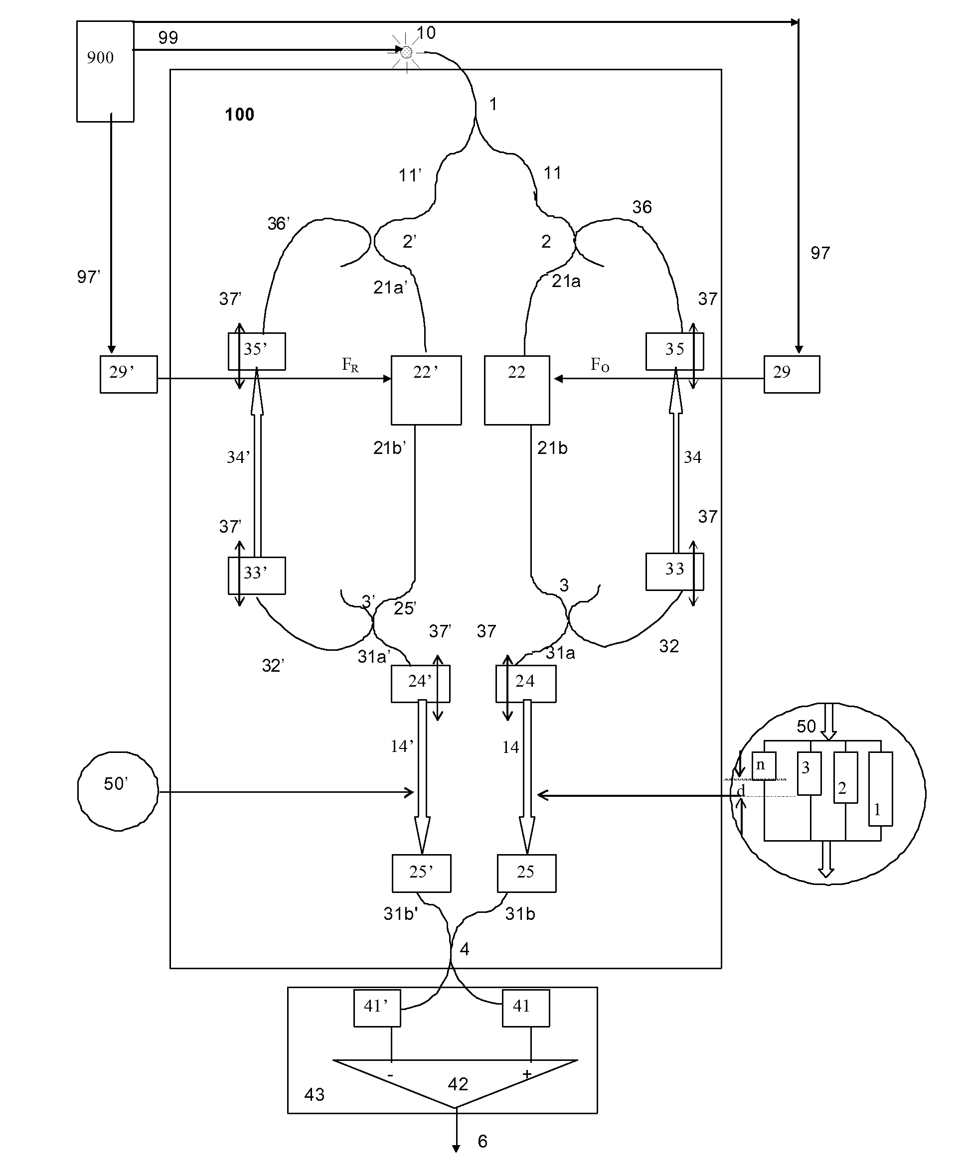
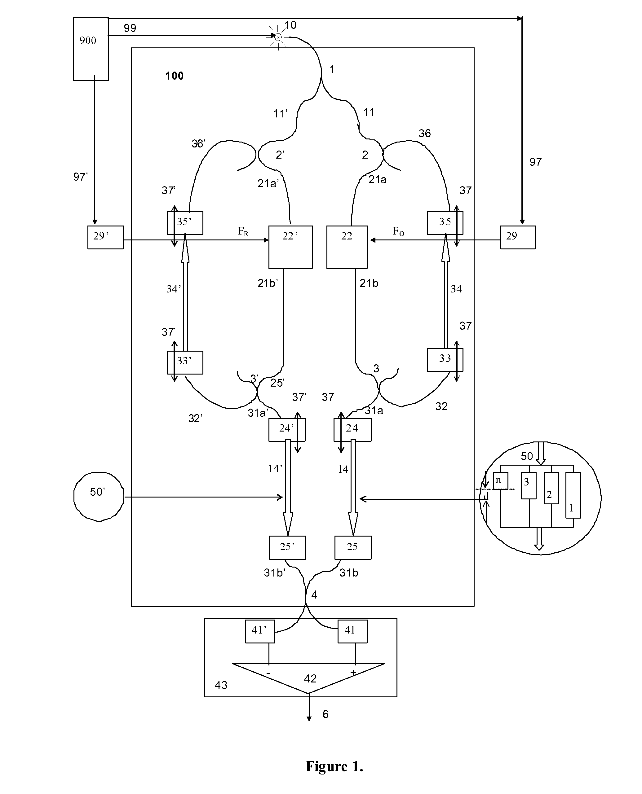
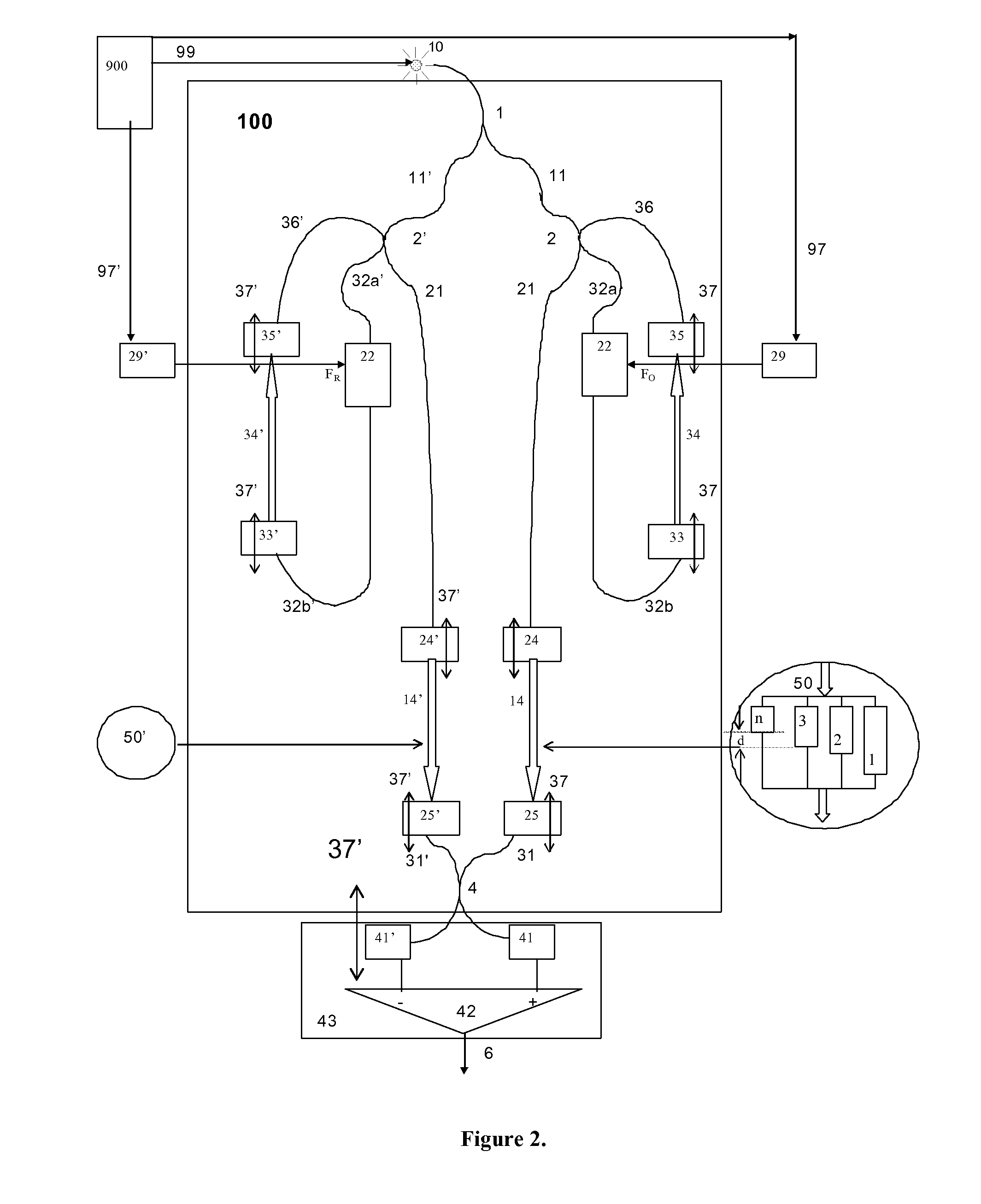
[0051]FIG. 1 shows, in diagrammatic form, the main elements of the multipath recirculating interferometer 100, here light from an optical source, 10, is divided into two beams, object and reference, at the output of a first splitter, 1, wherefrom light from one of its output feeds the main object path formed from path 11, of optical length s11, towards a 2nd splitter, 2, via another part of the main object path, 21a, of length d21a, towards an object modulator 22, which can be a frequency shifter or a phase modulator, of optical path length, d22, modulated at a frequency FO, along path 21b, of length d21b, towards the 3rd object splitter,...


PUM


Abstract

The invention discloses an optical interferometer which can be used to provide simultaneous measurements over multiple path lengths and methods to employ such an interferometer as to achieve a variety of functions covering simultaneous measurements at different depths separated by an increment of a multiple differential delay matched in the interferometer as well as imaging. Optical sensors, optical coherence tomography (OCT) set-ups, optical sensing methods and OCT methods are disclosed which can provide: (i) multiple en-face images at several depths with dynamic dispersion compensation, (ii) fast acquisition of cross sections, (iii) fast acquisition of 3D volumes of a scattering object while maintaining dynamic focus; (iv) fast acquisition of long axial measurement profiles, non mechanical, with dynamic focus, range scalable, with applications in tracking and OTDR. Methods are disclosed on the combination of scanning regimes and modes of operation to achieve versatile functionality in measurements, in the 3D imaging of moving tissue such as the eye, heart, or moving embryos or functional / low noise imaging by making use of angular compounding or polarisation. A method for elimination of axial movement effects in measuring the flow profile is also disclosed.

Description

1. FIELD OF THE INVENTION[0001]The present invention relates to an optical interferometer which can be used to provide simultaneous measurements and simultaneous optical coherence tomography (OCT) images over multiple path lengths, using principles of low coherence interferometry. Optical amplification is used to compensate for losses. The invention is applicable to time domain and frequency domain low coherence interferometry as well as to time domain and frequency domain OCT.2. BACKGROUND OF THE INVENTION[0002]In the description which follows, reference is made primarily to the eye. This has to be understood as merely a way to help the description and not as a restriction of the application of the present invention. As such, where the term “eye” is used, a more general transparent and scattering object or organ may be sought instead, the invention could equally be applied to skin, heart, vessels, embryos, dental tissue, dental prostheses, paintings, powders and other scattering se...

Claims


Application Information

Patent Timeline
Patent Type & Authority Applications(United States)
IPC IPC(8): G01B9/02
CPCA61B3/102A61B5/0059A61B5/0066A61B5/7257G01N21/4795G01B9/02028G01B2290/35G01B9/02002G01B9/02091G01B9/02014G01B2290/70G01B9/02087G01B2290/45G01B9/02044
Inventor PODOLEANU, ADRIAN
Owner UNIVERSITY OF KENT
Why Eureka
Try Eureka