Auto calibration / validation of oxygen sensor in breathing apparatus

a technology of oxygen sensor and breathing apparatus, which is applied in the direction of respirator, operating means/releasing devices of valves, underwater equipment, etc., can solve the problems of increased risk of hyperoxia-induced seizure and other “oxygen toxicity” symptoms, increased risk of decompression sickness, and increased volume of gas injected

Active Publication Date: 2011-05-19
POSEIDON DIVING SYST
View PDF24 Cites 18 Cited by
  • Summary
  • Abstract
  • Description
  • Claims
  • Application Information

AI Technical Summary

Benefits of technology

For example, an oxygen control system according to an embodiment of the present invention incorporates two oxygen sensors (one may be designated as the “Primary Sensor”, and the other may be designated as the “Secondary Sensor”) and a minimum of three electronically controlled gas valves: two used to inject oxygen, and one used to inject “diluent” gas (i.e., a mixture containing primarily non-oxygen but nonetheless constituting a gas mixture that is directly breathable in open circuit mode within some regime of a planned dive—typically it is designed to be breathable at the maximum planned dive depth). The “diluent” gas supply may e.g. be air (˜21% oxygen, ˜79% nitrogen and other trace gases), but any breathable mixture containing at least some (known) oxygen fraction will serve the same purpose. It should be added that oxygen gas has a fraction of oxygen that is 1 or nearly 1 (i.e. 100% or nearly 100% oxygen). As indicated above, the it is preferred that the oxygen control system periodically validates the readings of the Primary Sensor using controlled direct injections of either oxygen or diluent (depending on the depth and the circumstances) and monitoring the response of the sensor to validate accurate readings. It is also preferred that these gas injections also serve the purpose of removing any condensation that may form on the face of the sensors, thus eliminating one of the common failure modes described above. It is also preferred that the Secondary Sensor is used to monitor the oxygen content of the breathing gas while the Primary Sensor is being validated, and also to safeguard against possible failure modes of the Primary Sensor validation system, e.g. possible leakage in the control valves that inject oxygen or diluent onto the primary sensor which would cause faulty oxygen readings.
Since it is preferred that the primary sensor in the present invention has direct access to both oxygen and known diluent mixtures (e.g., air) via electronically-controlled microvalves, the system is capable of calibrating itself without any input from the user and it is capable of performing the calibration with an exceedingly small volume of consumable gas, which is an important performance measure in CCR systems and which allows these systems to be substantially more compact than open circuit systems providing equivalent diving range at a given depth. Nor do preferred embodiments of the present invention require any reliance of proper user-initiated calibration routines or any interaction of the user at all. At initial power-up, the system will automatically inject a burst of pure diluent gas (e.g., air) directly on the primary Oxygen Sensor, reliably exposing it to a known low-oxygen mixture. If a diver is not breathing on the CCR breathing loop at the time of calibration, then a sufficient volume of diluent gas can be injected to also expose the nearby Secondary Oxygen Sensor. The same procedure applies to the oxygen supply mixture as well. These two known points provide a precise 2 point calibration for the primary oxygen sensor.
Preferred embodiments of the invention described here—because of the availability of oxygen and diluent (e.g., air) directly applied to the primary Oxygen Sensor via the electronically-controlled Oxygen Test Valve and Diluent Test Valve, and the proximity of the Secondary Oxygen Sensor to the Primary Oxygen Sensor—are much more effective and efficient for establishing accurate calibration of the oxygen sensors prior a dive. Additional embodiments of the invention have been made even more reliable by:1) incorporating threshold limits to detect when a sensor falls out of acceptable output voltage values at calibration time;2) use of algorithmic analysis of a stored log of calibration values to detect calibration trends, alerting the user to a need to replace a sensor; and3) clear “Do not Dive” indicators that prevent the user from operating the system in the event that the pre-dive calibration process does not complete successfully.
An additional benefit of the automatic pre-dive check as indicated above is that it can also serve as a pre-dive verification that the correct gas mixture (oxygen or diluent) is connected to the correct supply regulator (within calibration threshold tolerances of the sensors).
Because embodiments of the system also has access to 100% oxygen and can inject it directly onto the Primary Oxygen Sensor, the system is also capable of testing the linearity of the sensor voltage output at partial pressures in excess of 1 bar (i.e., the maximum calibration value during pre-dive). For example, when the Electronic Control System detects via an ambient pressure sensor that the diver has reached a depth of 20 feet (6 m), where the ambient pressure is approximately 1.6 bar, a small burst of oxygen directly on the Primary Oxygen Sensor can ensure that the calibration constants apply reliably for readings at partial pressures well above 1.0 bar. Thus, if the system is set to maintain an oxygen partial pressure of 1.3 bar, there can be confidence in the reliability of the readings at that value, even though it is higher than the maximum pre-dive calibration value of 1.0 bar. As with the diluent injections, the volume of oxygen needed to be injected to perform this test is so small that it would not have a significant impact on the overall gas composition in the CCR breathing loop. Hence, embodiments of the invention described herein offer a full range sensor calibration extending beyond the typical calibration performed on the surface at 1 bar. Furthermore, this calibration can be performed in a fully automated fashion that is “transparent” to, and requires no interaction from, the user.

Problems solved by technology

If the oxygen partial pressure exceeds a certain threshold (approximately 1.4 bar) the high concentration of oxygen and the risk of hyperoxia-induced seizure and other “oxygen toxicity” symptoms is considered unsafe for the diver.
It is these non-oxygen components of the breathing mixture that lead to problems of decompression sickness (DCS), also known as “the bends”, which include symptoms ranging from pain in the joints, to paralysis, to death.
But this advantage comes at a cost.
Although it is this dynamic mixture capability that affords the CCR one of its primary advantages, a failure of the oxygen control system can be extremely dangerous.
A malfunction that allows the PO2 to get too high places the diver at risk of a hyperoxia-induced seizure, which would almost certainly cause the diver to drown.
A malfunction that allows the PO2 to get too low may lead to hypoxic-induced blackout, causing the diver to drown and / or suffer severe brain damages.
There are a number of ways that oxygen sensors—considered by most experienced CCR divers as the weakest link in the oxygen control system—can fail (i.e., provide false readings), e.g. due to faulty calibration, sensor failure or condensation etc.
If a sensor falls out of proper calibration the electronic control system of a CCR will misinterpret the readings.
Galvanic oxygen sensors eventually fail either through exhaustion of their chemical reaction or other age related degradation of active sensing elements and / or from a host of other environmental and user-caused effects (e.g. abuse, improper use).
Because the calibration process of most CCR systems uses 100% oxygen at ambient pressure (i.e, 1 bar partial pressure) in a pre-dive calibration, the calibration process may appear to complete correctly, but the system may not be able to properly interpret readings when the sensor is exposed to oxygen partial pressures above 1 bar.
Moreover, one of the most common modes of oxygen sensor failure involves condensation.
As a consequence, the inside walls of the CCR breathing pathways are typically dripping wet with condensation after a short period of time.
This condensation can affect the oxygen sensor and cause erroneous readings.
It can also lead to premature failure of the sensor.
This is among the most dangerous forms of oxygen sensor failure, because it provides a false but plausible reading to the electronics, concealing the nature of the failure.
Conversely, if the trapped pocket of gas has a PO2 above the “setpoint” value, the control system will fail to add any oxygen at all, and the PO2 of the breathing gas will gradually diminish due to the diver's metabolic oxygen consumption, until hypoxic levels are reached and the diver blacks out.
This is i.a. based on the notion that if only one oxygen sensor is used, and it fails in a way that gives otherwise plausible readings, then there is no logical way to recognize that the sensor has failed.
Similarly, if two sensors are used and one of them is giving a false reading, the control system can logically recognize a problem (unless both sensors fail in the same way), but cannot determine which sensor is correct and which has failed.
Though ubiquitous among modern rebreather designs, the three-sensor approach to monitoring oxygen concentration in the breathing mixture is far from perfect.
Because sensor readings can be slightly unstable in the chaotic breathing gas mixture of a CCR, a sensor must deviate from the other two sensors by a certain minimum threshold amount before it is considered suspect.
Another problem with reliance upon the triple-redundant oxygen sensor system is the fact that sometimes two sensors fail the same way—often due to asymmetric condensate formation or because a user may have replaced one sensor with a fresh one and the other two are at the end of their useful life but may have exhibited in-range readings prior to the start of a dive (there are many such possibilities)—such that the apparently errant sensor reading is actually the correct reading.
This mode of failure is particularly dangerous in that the control system actively ignores the true reading.
Indeed, there have even been documented cases where all three sensors fail simultaneously such that all three give the same, but false reading.
Although using three oxygen sensors and using sensors designed specifically for humid environments can mitigate some of the problems indicated above, all known CCR oxygen control systems are subject to failures due to one or more of the above problems.

Method used


Image

  • Auto calibration / validation of oxygen sensor in breathing apparatus
  • Auto calibration / validation of oxygen sensor in breathing apparatus
  • Auto calibration / validation of oxygen sensor in breathing apparatus

Examples


Embodiment Construction

Basic Breathing Apparatus

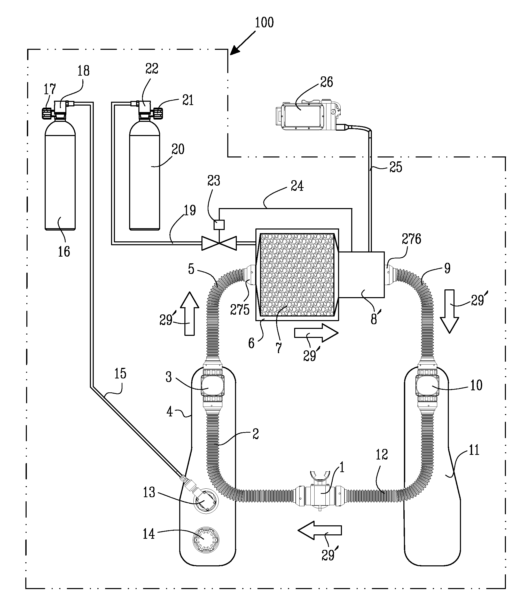
FIG. 1 shows in schematic mode of an exemplifying breathing apparatus 100 in the form of a typical modern CCR architecture, e.g. as elaborated in the patent document U.S. Pat. No. 4,964,404 (Stone). The general operation of such a CCR is as follows: the user breathes into a mouthpiece 1 that contains checkvalves (not shown) that enforce the flow of gas in a preferential direction, as schematically indicated by the arrows 29′ in FIG. 1. The expelled gas (from exhalation) travels down breathing hose 2 and into junction block 3, which permits passage of the gas into a flexible bladder 4 known as a “counterlung”. In advanced CCR designs (e.g. as in the patent document by Stone cited above) two counterlungs are used—an exhalation counterlung 4 and an inhalation counterlung 11 such that each has a volume equal to about half the exhalation volume of the diver. As the exhalation counterlung 4 fills the gas then continues through junction block 3 and through breathin...


PUM


Abstract

The Invention is directed to an oxygen sensor arrangement (8) and a method for operating such an arrangement for sensing the oxygen in a breathing loop (29) of a breathing apparatus. The sensor arrangement comprises: at least one primary oxygen sensor (30) arranged to operatively measure the oxygen in the breathing loop (29), at least a secondary oxygen sensor (31) arranged to operatively measure the oxygen in the breathing loop (29), and a control arrangement (40) for obtaining measures from said oxygen sensors. A test channel arrangement (15, 48) is adapted to operatively provide a first gas having a first fraction of oxygen from a first gas supply (16) to said primary oxygen sensor (30) at a position (267) adjacent to said primary oxygen sensor (30). At least a first test valve arrangement (41, 42) is arranged to operatively open and close the flow of said first gas through said test channel arrangement (15, 48). Said control arrangement (40) is arranged to operatively actuate said first test valve arrangement (41, 42) so as to provide an amount of said first gas to said primary oxygen sensor (30) via said test channel arrangement (15, 48). Said control arrangement is arranged to operatively obtain measures from said primary (30) and secondary (31) oxygen sensors.

Description

TECHNICAL FIELDThe present invention relates to breathing apparatuses and the control of oxygen in such breathing apparatuses.BACKGROUNDIt is well known to those skilled in the art that breathing apparatuses such as fully closed-cycle breathing apparatuses and similar—e.g. the specific sub-genre known as fully closed-cycle underwater breathing apparatus (CCUBA) or alternatively known as “closed-circuit rebreathers” or “CCR”—offer distinct advantages over the more common open-circuit breathing apparatuses such as e.g. Self-Contained Underwater Breathing Apparatuses (SCUBA) and the like. It should be emphasised that even if the text herein may focus on closed-cycled breathing apparatuses for diving purposes the same or similar advantages applies mutatis mutandis for closed-cycled breathing apparatuses in general and other breathing apparatuses wherein the amount of oxygen in the breathing gas has to be controlled.Advantages provided by closed-cycle breathing apparatuses and similar ar...

Claims


Application Information

Patent Timeline
Patent Type & Authority Applications(United States)
IPC IPC(8): A61M16/00
CPCA61M16/12A61M16/22A61M2016/1025A61M2202/0208A61M2205/17A61M2205/502A61M16/203A61M2205/8206B63C11/24A62B9/006B63C11/12A61M16/122A61M2205/702A61M2230/435A61M16/085
Inventor STONE, WILLIAM C.JONES, NIGEL
Owner POSEIDON DIVING SYST
Why Eureka
Try Eureka