Apparatus and method for treating ballast water

a ballast water and apparatus technology, applied in the nature of the treatment water, multi-stage water/sewage treatment, separation process, etc., can solve the problems of high cost of use electrodes, easy pollution of electrobath, and destruction of the body of the ship

Inactive Publication Date: 2011-05-19
SAMSUNG HEAVY IND CO LTD
View PDF12 Cites 31 Cited by
  • Summary
  • Abstract
  • Description
  • Claims
  • Application Information

AI Technical Summary

Problems solved by technology

In other words, if a ship does not have a predetermined weight, the draft line is lowered to the lower portion of the ship by means of buoyancy, thereby causing some problems that the propeller of the ship is exposed to fail to obtain a propelling force, a wave resistance force during the voyage is lowered to apply much load to the voyage, and the body of the ship is destroyed.
To the contrary, it has some disadvantages in that a high quality of filter is required, the cost of the usage electrode is high, the disinfectant do not have any residual property so that the disinfection is needed again at the time of discharging ballast water, the electrobath is easily polluted, a test for the disinfection effects is required, and hydrogen gas is explosive because of the flow of generated hydrogen into the ballast tank.
To the contrary, it has some disadvantages in that the control of disinfection is difficult, the disinfection speed is low, the residual products after the disinfection are made, the neutralization of the disinfectant is needed, the electrobath is easily polluted, the hydrogen gas is explosive because of the flow of generated hydrogen into the ballast tank, and the electrolysis efficiency is sensitive to a quality of water.
To the contrary, it has some disadvantages in that the disinfection speed is low, the residual products after the disinfection are made, the neutralization of the disinfectant is needed, all of which are common in the direct and indirect chlorine electrolysis, and the injection of a neutralizing agent is needed together with the addition of chemicals in other chemical treatments.
In the conventional methods for treating ballast water, however, the indirect electrolysis of seawater as shown in FIG. 13 does not have any means for precisely controlling an amount of disinfectant to be injected in accordance with a flow rate of the ballast water flowing into the ballast tank, so that the ballast water not treated, that is, the ballast water containing pollution sources may flow into the ballast tank.
Additionally, the prior art apparatus does not have any means for processing hydrogen gas generated after the electrolysis from the generator in which the electrolysis for the seawater is performed to generate the sodium hypochlorite therefrom, so that if the hydrogen gas is accumulated, it may be exploded in the ballast tank.
At this time, the generator generating the sodium hypochlorite may be polluted.
However, the prior art apparatuses do not have any means for preventing the generator from being polluted, thereby causing the durability of the apparatus to be lowered.
In this case, the concentration-decreased disinfectant during the idle time after the activation of the equipment is just injected without ...

Method used


Image

  • Apparatus and method for treating ballast water
  • Apparatus and method for treating ballast water
  • Apparatus and method for treating ballast water

Examples


second embodiment

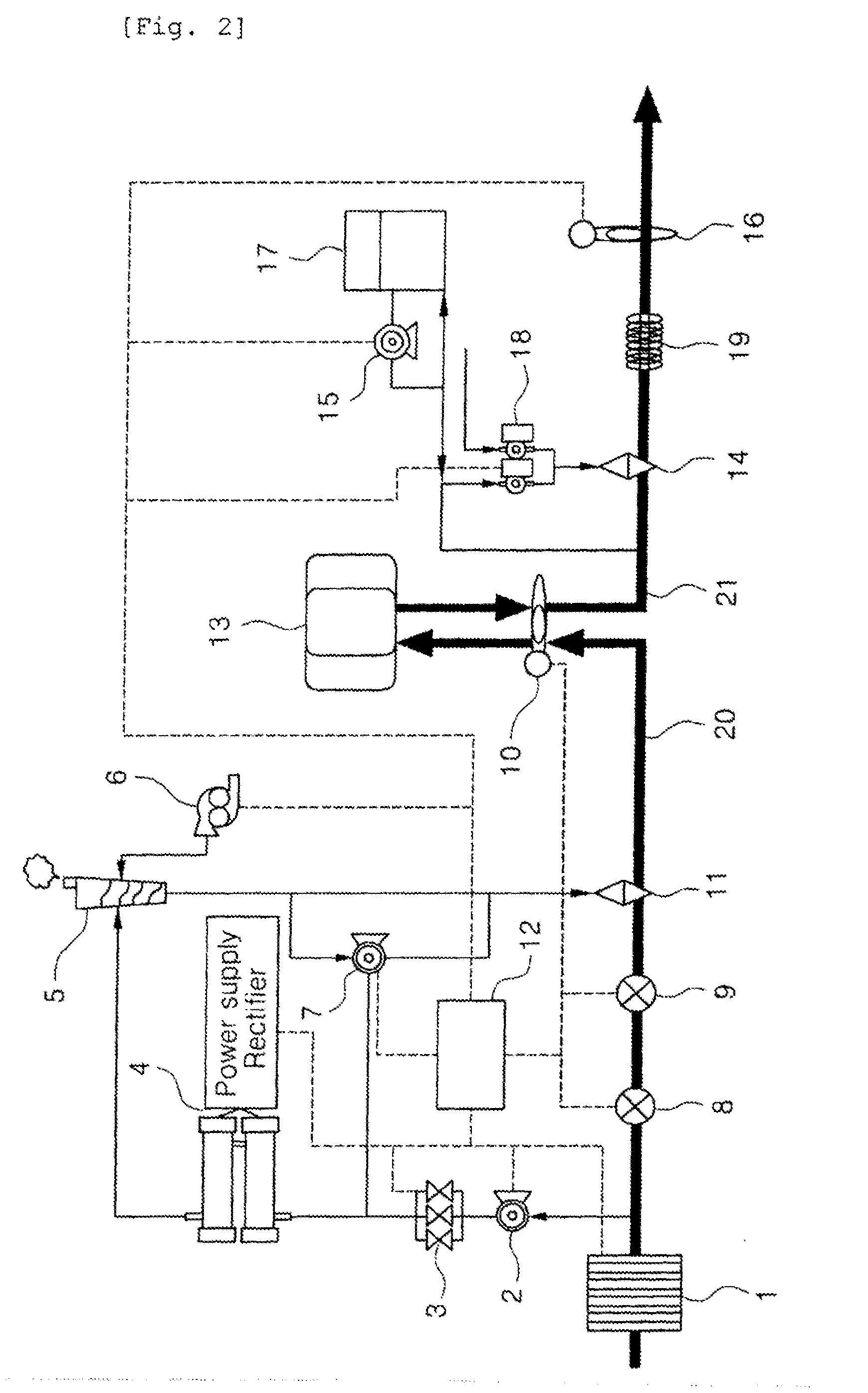
FIG. 2 is a circuit diagram showing a schematic configuration of an apparatus for treating ballast water according to the present invention, wherein most of the configuration thereof is the same as that in FIG. 1. Hereinafter, only components different from those in FIG. 1 will he explained.

According to a second embodiment of the present invention, the apparatus for treating ballast water further includes a cleaning / injection pump 7 connected at one side thereof to the line branched from the sodium hypochlorite supply line between the gas-liquid separator 5 and the automatic injector 11 and connected at the other side thereof to the line branched between the flow rate control valves 3 and the electrolysis module 4, so as to continuously or periodically circulate the sodium hypochlorite passed through the gas-liquid separator 5 to the electrolysis module 4 in which the production of the sodium hypochlorite stops.

If the activation of the electrolysis module 4 stops, the ballast water ...

third embodiment

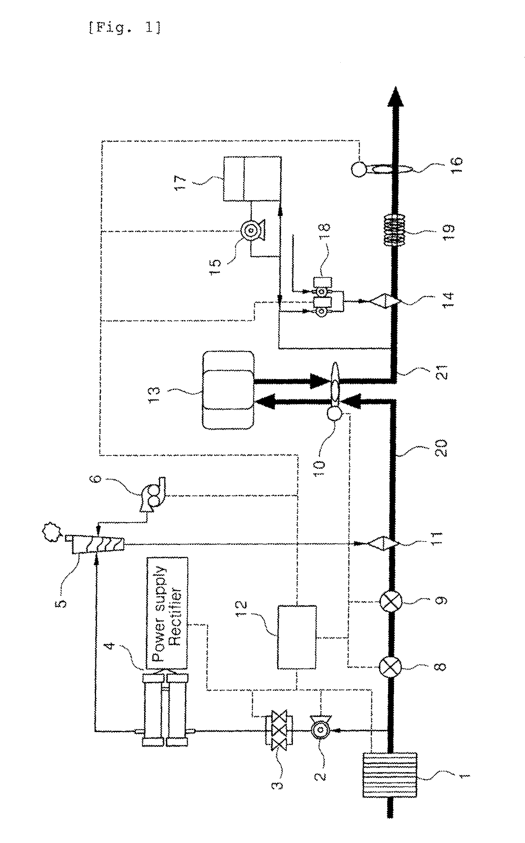
FIG. 3 is a circuit diagram showing a schematic configuration of an apparatus for treating ballast water according to the present invention, wherein most of the configuration thereof is the same as that in FIG. 1.

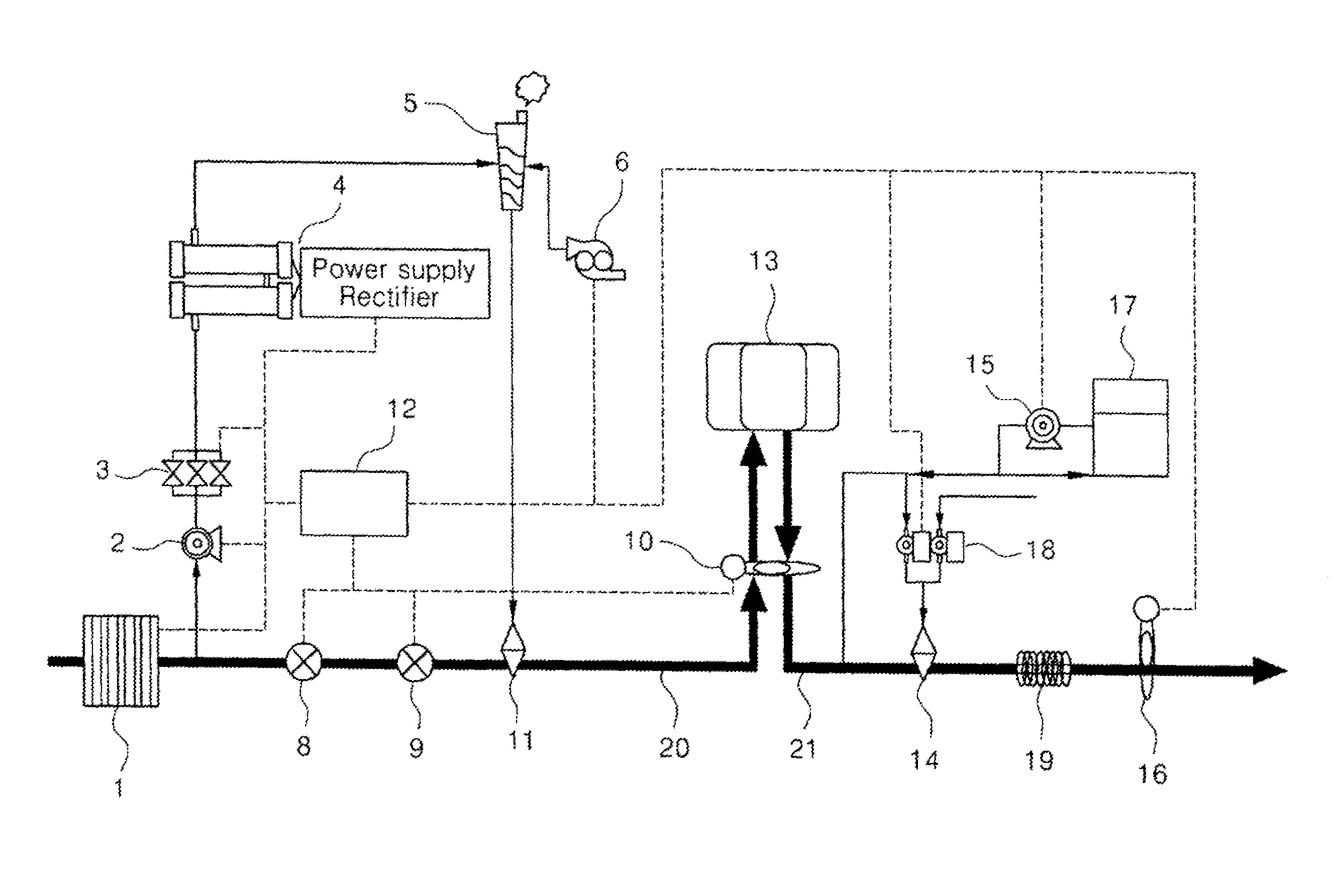
According to the third embodiment of the present invention, however, the apparatus is provided at the back portion of the ballast tank 13, and therefore, the residual chlorine measurer 10, as shown in FIG. 1, which is disposed in the seawater intake and discharge lines 20 and 21 at the front and back of the ballast tank 13, is not provided therein. Instead of the formation of the residual chlorine measurer 10, the pre-processing filter 1 as shown in FIG. 1 is disposed in the seawater line at the front of the ballast tank 13, and after the formation of the ballast tank 13, a branch pipe is disposed between the salinometer 8 and the flow rate meter 9 and is connected to the electrolysis module 4 wherein the sodium hypochlorite is produced. Then, the ballast water is passed th...

fourth embodiment

FIG. 4 is a circuit diagram showing a schematic configuration of an apparatus for treating ballast water according to the present invention, wherein since the basic configuration and operating principles thereof are the same as those in FIG. 2, and an explanation on them will be avoided.

FIG. 5 is a circuit diagram showing a schematic configuration of an apparatus for treating ballast water according to a fifth embodiment of the present invention, wherein the basic configuration thereof is the same as that in FIG. 1, except that the seawater used to produce the sodium hypochlorite is not supplied from the seawater intake line 20 flowing to the ballast tank 13 but supplied selectively from a cooling seawater line before heat exchange 22 and from a cooling seawater line after heat exchange 23.

Generally, the seawater used for other proposes as well as the ballast water exist in the ship. That is, when various equipment and an engine in the ship are cooled, freshwater is used for direct ...


PUM

PropertyMeasurementUnit
Fractionaaaaaaaaaa
Fractionaaaaaaaaaa
Fractionaaaaaaaaaa

Abstract

An apparatus and method for precisely controlling production, injection, and removal of disinfectants using electrolysis according to the flow rate of ballast water are provided, where the ballast water flows into or is discharged from the ballast tank to manage the ballast water or ships so that destruction or disruption of marine ecosystems can be prevented. An apparatus for treating ballast water and treatment method using the same are provided, the apparatus including: an electrolysis module for producing concentration-controlled sodium hypochlorite; a gas-liquid separator for separating hydrogen gas; a micro bubble generator for mixing and supplying reducing agents while reducing residual chlorine; a vortex generator for generating vortex; and a control system. The control system controls a salinometer, a flow rate meter, a residual chlorine meter, a seawater supply pump, flow rate control valves, an electrolysis module, a residual chlorine meter, a micro bubble generator, and an injection pump.

Description

TECHNICAL FIELD The present invention relates to an apparatus and a method for treating ballast water, and more particularly, to an apparatus and a method for treating ballast water that performs the electrolysis for the seawater from which aquatic organisms, bacteria and general microorganisms are removed at the time of flowing the seawater as the ballast water into a ballast tank during a voyage of a ship, produces a disinfectant through the electrolysis, injects the produced disinfectant into the seawater through precise control to purify the flowing seawater, performs a reducing process for the ballast water discharged from the ballast tank to sea with a reducing agent through precise and reliable control, and discharges the ballast water in a state of harmlessness to the sea.BACKGROUND ART In general, ships such as oil tankers, cargo ships and so on carry cargos like oil to an importing country, and after the cargos are unloaded on a port of the importing country, the ship stor...

Claims


Application Information

Patent Timeline
IPC IPC(8): C02F9/04C02F1/467C02F1/76C02F1/70
CPCC02F1/4674C02F1/70C02F2209/40C02F2209/05C02F2209/29C02F2103/008B63J99/00C02F1/467C02F1/50C02F2103/08C02F2303/04C02F2305/02
Inventor KIM, JUNG SIKJUNG, EUI YONGKIM, DONG SUNGJUNG, BOONG IK
Owner SAMSUNG HEAVY IND CO LTD
Why Eureka
Try Eureka