
Substrate processing method, substrate processing apparatus and storage medium storing program

a substrate processing and substrate technology, applied in the direction of resistive material coating, superimposed coating process, liquid/solution decomposition chemical coating, etc., can solve the problem of non-uniform critical dimension (cd) of patterns formed after etching, failure to obtain design device characteristics, and critical dimension deviation of hole or trench from target value, etc. problem, to achieve the effect of increasing the flow rate of gas, reducing the degree of non-uniformity of deposition on the surface of substra

Inactive Publication Date: 2011-05-19
TOKYO ELECTRON LTD
View PDF10 Cites 34 Cited by
  • Summary
  • Abstract
  • Description
  • Claims
  • Application Information

AI Technical Summary

Benefits of technology

[0008]In view of the foregoing, the present disclosure provides a substrate processing apparatus capable of effectively suppressing non-uniformity in deposition degree on a surface of a substrate even if an internal pressure of a processing chamber is increased.
[0014]In accordance with the present disclosure, in the depositing process performed prior to the etching process, by increasing the flow rate of the gas greatly as compared to a conventional flow rate, non-uniformity in deposition degree on the surface of the substrate can be effectively suppressed even if the internal pressure of the processing chamber is increased. Accordingly, the deposit can be uniformly deposited on the sidewall of the opening of the resist pattern, and uniformity in deposition degree on the surface of the substrate can be improved.

Problems solved by technology

Along with the miniaturization of the semiconductor device, there has occurred a problem that when an etching target film on a substrate is etched by using a resist pattern as a mask, dimensions of the opening of the resist pattern may be enlarged or a sidewall of a recess in the etching target film may be overetched, resulting in a deviation of a critical dimension (CD) of a hole or a trench from a target value and a failure to obtain designed device characteristics.
In the deposition process, however, as the internal pressure of the processing chamber increases, critical dimensions of patterns formed after the etching was observed to become non-uniform.
As the internal pressure of the processing chamber increases, dissociation of the processing gas may be facilitated, and, thus, a difference in dissociation degree of the processing gas may be generated in a diametric direction of the substrate, which in turn may cause non-uniformity in deposition degree on the surface of the substrate.
Thus, the non-uniformity in the critical dimensions of the patterns on the substrate is deemed to be caused by such non-uniformity in the deposition degree on the surface of the substrate.
Although the non-uniformity of the critical dimensions is in the order of nanometer (nm), such a slight degree of non-uniformity may not be regarded negligible to meet a demand for further miniaturization of the patterns.

Method used


Image

  • Substrate processing method, substrate processing apparatus and storage medium storing program
  • Substrate processing method, substrate processing apparatus and storage medium storing program
  • Substrate processing method, substrate processing apparatus and storage medium storing program

Examples


Embodiment Construction

[0037]Hereinafter, embodiments of the present disclosure will be explained in detail with reference to accompanying drawings. Through the present specification and drawings, parts having substantially same function and configuration will be assigned same reference numerals, and redundant description will be omitted.

[0038](Configuration Example of a Substrate Processing Apparatus)

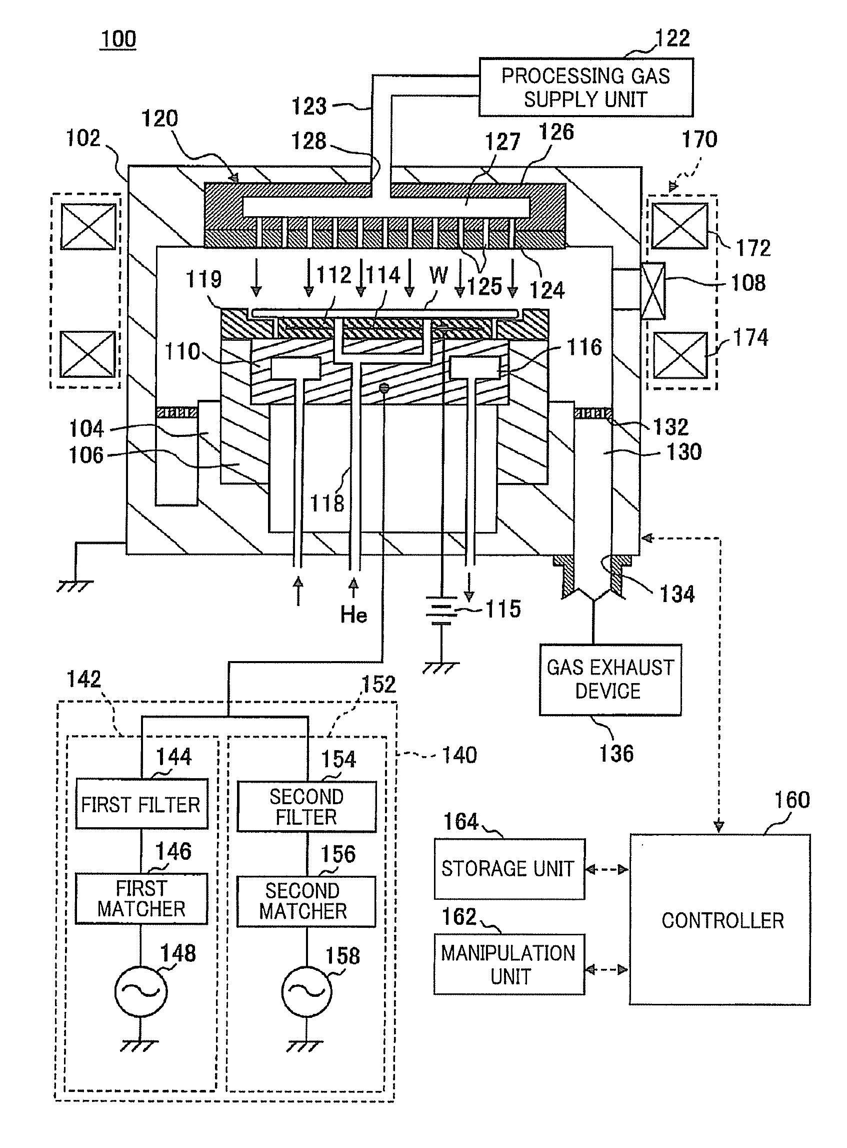
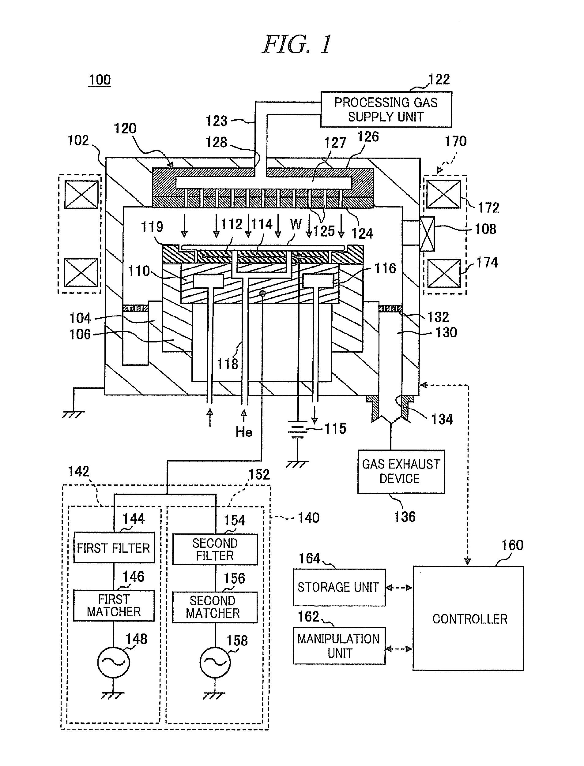
[0039]Above all, a configuration example of a substrate processing apparatus in accordance with an embodiment of the present disclosure will be explained with reference to the drawings. Herein, there will be explained a substrate processing apparatus configured as a plasma processing apparatus in which an etching target film on a wafer W is etched by applying a first high frequency power (high frequency power for plasma generation) of a relatively high frequency of, e.g., about 40 MHz and a second high frequency power (high frequency power for a bias voltage) of a relatively low frequency of, e.g., about 13....


PUM

PropertyMeasurementUnit
Pressureaaaaaaaaaa
Pressureaaaaaaaaaa
Flow rateaaaaaaaaaa

Abstract

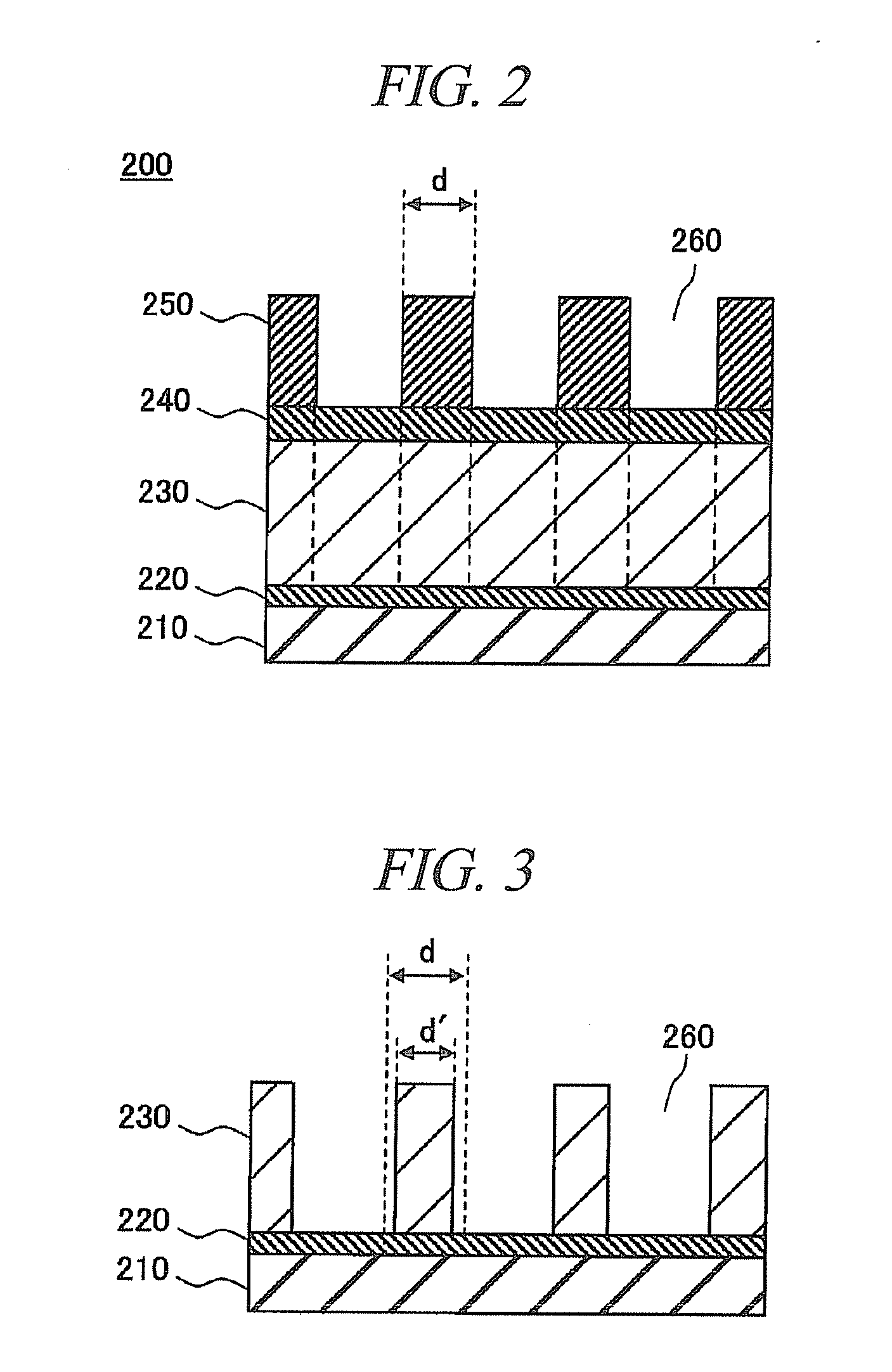
There is provided a substrate processing apparatus capable of effectively suppressing non-uniformity in deposition degree on a surface of a substrate. A substrate processing method includes depositing a deposit on a sidewall of each opening of a resist pattern, which is formed on an antireflection film on an etching target film of the substrate and is provided with a plurality of openings, before etching the etching target film of the substrate. Plasma is generated in the depositing process by introducing a CHF-based gas into the processing chamber at a flow rate equal to or higher than about 1000 sccm while a pressure in the processing chamber is set to equal to or higher than about 100 mTorr.

Description

CROSS-REFERENCE TO RELATED APPLICATION[0001]This application claims the benefit of Japanese Patent Application No. 2009-261018 filed on Nov. 16, 2009 and U.S. Provisional Application Ser. No. 61 / 296,314 filed on Jan. 19, 2010, the entire disclosures of which are incorporated herein by reference.FIELD OF THE INVENTION[0002]The present disclosure relates to a substrate processing method and a substrate processing apparatus for performing a deposition process for depositing a thin film on a substrate such as a semiconductor wafer or a FPD substrate and also relates to a storage medium.BACKGROUND OF THE INVENTION[0003]In a manufacturing process of a semiconductor device or a flat panel such as a liquid crystal display, a desired microscopic structure (e.g., holes, trenches, or the like) pattern is formed on a substrate such as a semiconductor wafer or a FPD substrate by performing various processes such as a film forming process and an etching process on the substrate. Recently, the sem...

Claims


Application Information

Patent Timeline
IPC IPC(8): H05H1/00
CPCC23C16/045C23C16/455H01J37/3266H01J37/32091H01J37/32165C23C16/52
Inventor HONDA, MASANOBU
Owner TOKYO ELECTRON LTD
Learn More