Aortic dissection septal cutting tool

a cutting tool and aortic dissection technology, applied in the field of aortic dissection septal cutting tools, can solve the problems of severe complications and/or death, failure of blood vessels, and limited surgical ability to treat type b thoracic aortic dissections, and achieve the effect of precise cuts and little or no damage or trauma

Active Publication Date: 2011-05-19
WL GORE & ASSOC INC
View PDF15 Cites 22 Cited by
  • Summary
  • Abstract
  • Description
  • Claims
  • Application Information

AI Technical Summary

Benefits of technology

[0010]As described above, dissections cause formation of a false lumen in a blood vessel, or other anatomical structure, from tissue defining a true lumen. One approach to treating dissections is cutting the septum to open the false lumen. Opening the false lumen permits any contents of the lumen to be removed. A severed septum also limits or prevents further collection of fluid, such as blood, in the false lumen. The present invention readily accesses, engages, and controllably cuts tissue of a dissection with little or no damage or trauma to adjacent tissues and anatomical structures.
[0011]The present invention has a cutting blade assembly for engaging septal tissue separating a false lumen from a true lumen in a dissection. The cutting blade assembly has at least one cutting blade held by a movable housing. The movable housing is remotely actuated with an elongate member. The elongate member usually runs the length of a delivery catheter and terminates with a control knob, handle, or hub. In some embodiments, a flexible housing member is attached to the cutting blade assembly. When the cutting blade assembly portion of the invention is positioned in proximity to tissue of a septum in a dissection, the invention can be manipulated to introduce the flexible housing member into the false lumen. Once the flexible housing member is located in a false lumen, the cutting blade is...

Problems solved by technology

Failure of a blood vessel can involve separation of an inner layer of the blood vessel wall from the remaining outer layers of the blood vessel wall.
However, damage to the aorta wall due to a dissection can lead to severe complications and/or death.
The ability to treat Type B thoracic aortic dissections surgically is often limited.
The difficulty in performing surgical cuts of this nature inside such a mechanically and biologically compromised aorta, or other major blood vessel, limits the number of ...

Method used


Image

  • Aortic dissection septal cutting tool
  • Aortic dissection septal cutting tool
  • Aortic dissection septal cutting tool

Examples


example 1

[0082]A catheter-based dissection septal cutting tool (1) of the present invention was constructed as follows (FIG. 12).

[0083]Initially, a cutting blade assembly (5) having a movable, or translatable, V-shaped cutting blade (4) was constructed (FIG. 7) and subsequently attached to a delivery catheter (6) as illustrated in FIG. 8. The movable cutting blade (4) is controlled and actuated with movable elongate member (2).

[0084]A cutting blade (4) for the cutting blade assembly (5) was made from a sheet of 316L stainless steel (0.25 mm thick) (McMaster Carr, Elmhurst, Ill.). The stainless steel sheet was cut into a rectangular section measuring 0.63 cm long and 0.24 cm wide. A 0.10 cm long V-shaped notch was center cut along the length of the section. The apex of the V-shaped cut had an angle of thirty-five (35) degrees. The edges of the V-shaped notch were sharpened using a grinder to form cutting blade (4).

[0085]A movable elongate member (2) for the cutting blade assembly (5) was made...

example 2

[0099]A cutting tool having a movable cutting blade and actuated, flexible, displacement elements was constructed as follows (FIGS. 14 and 15).

[0100]A delivery catheter (30) having one tubular component (31) placed inside another tubular component (32) in a coaxial relationship was obtained from W.L.Gore & Associates, Inc., Flagstaff, Ariz. The catheter is currently used in conjunction with the GORE VIABIL® Biliary Endoprosthesis.

[0101]The delivery catheter had a 3.07 mm outer diameter and is compatible with delivery systems and devices having diameters in the range of ten French (10 Fr). The delivery catheter has a component for mounting the GORE VIABIL® Biliary Endoprosthesis extending from one end of the catheter. The mounting component is a solid metallic shaft with a bulbous feature on the end of the shaft to assist in retaining the endoprosthesis on the shaft. The metallic shaft and bulbous feature were removed from the delivery catheter by cutting. The delivery catheter had a...

example 3

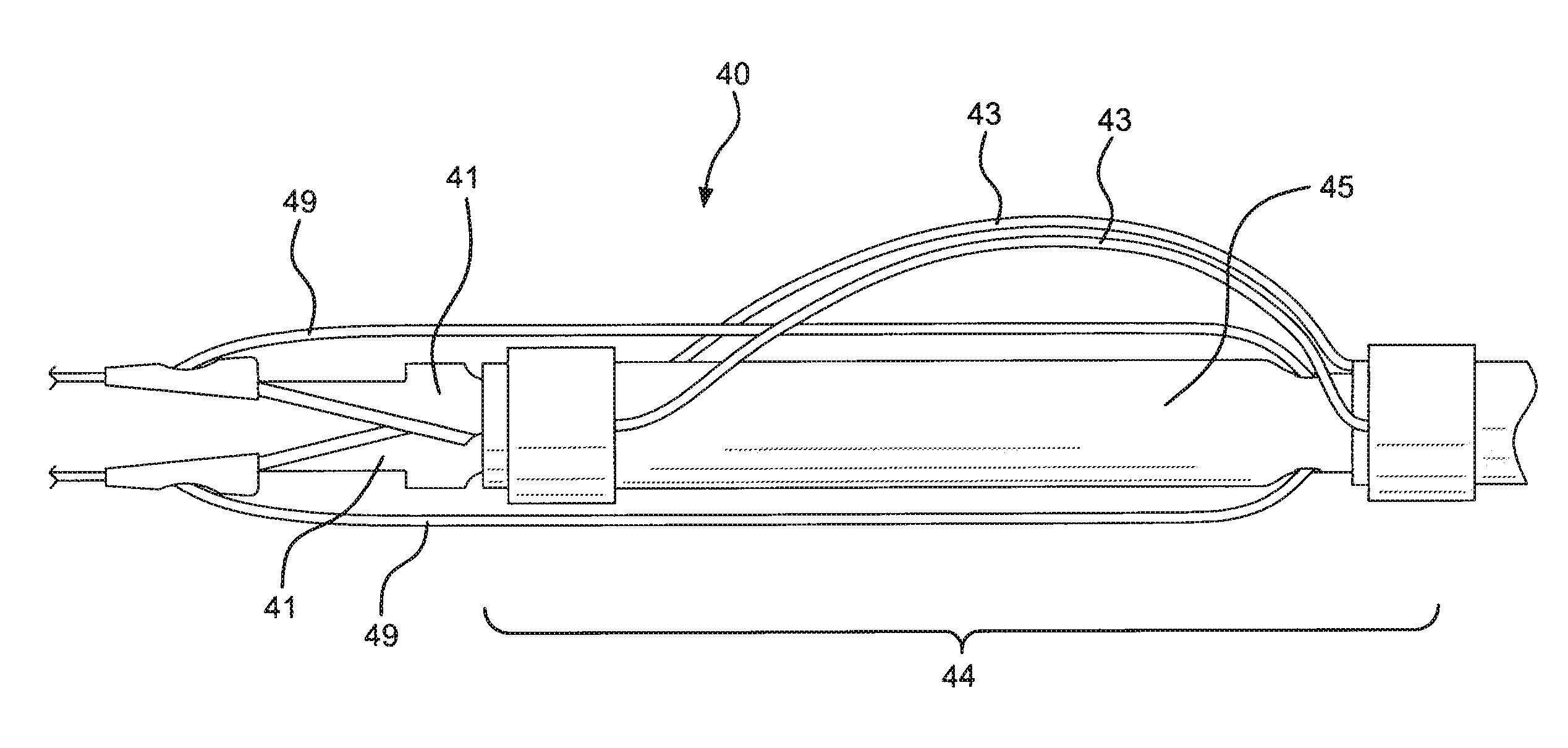
[0119]This example describes the construction of an embodiment of the present invention (40) having a cutting blade assembly (42) attached to a catheter (44) (FIG. 16). The cutting blade assembly (42) has a pair of remotely actuated scissor-like cutting blades (41). The invention also has a plurality of flexible displacement elements (43) attached to the cutting blade assembly (42) and the catheter (44).

[0120]Cutting blades (41) for the cutting blade assembly (42) were constructed as follows. A small bore stainless steel tube was obtained (1.6 cm long, 2.8 mm outer diameter, 2.4 mm inner diameter, Microgroup, Inc., Medway, Mass.). Approximately 1.5 mm from one end of the tube a 0.8 mm diameter hole was drilled through both walls of the tube. A 5.5 mm long, 1.5 mm wide slot was ground into the same end as the holes, perpendicular to the axis of the holes. A second slot of the same dimensions was ground into the opposite side of the tube. Two cutting blades were made from tool steel. ...


PUM


Abstract

The present invention relates to medical cutting tools for treating aortic septal dissections. The cutting tool is provided with a delivery catheter and has a remotely actuated cutting blade or cutting wire component. The cutting tool is provided with at least one displacement element. The displacement element assists in placement of the cutting tool at a desired location. The displacement element also assists in maintaining contact between the cutting blade and tissue being cut.

Description

BACKGROUND OF THE INVENTION[0001]Blood vessels of the mammalian body can be subject to a variety of diseases, traumas, and pathological conditions. In some cases, failure of blood vessels is an aspect of one or more of these conditions. Failure of a blood vessel can involve separation of an inner layer of the blood vessel wall from the remaining outer layers of the blood vessel wall. As the inner layer of blood vessel tissue peels away, a space is formed within the layers of the blood vessel tissue. The space usually fills with blood and expands to form two channels, with the peeled-away tissue residing between the two channels. One of the channels is a remnant of the original blood vessel and continues to function as a blood conduit. This anatomical structure is referred to as the true lumen. The blood-filled space delimiting the other channel is referred to as a false lumen. The delamination of tissue in this manner is referred to as a dissection. The tissue residing between the t...

Claims


Application Information

Patent Timeline
IPC IPC(8): A61B17/22
CPCA61B17/320016A61B17/3201A61B17/32075A61B18/1492A61M2025/0037A61B2017/22039A61B2017/22052A61B2017/22069A61M25/003A61B2017/00778
Inventor BLISS, CODY L.CULLY, EDWARD H.GREENE, JOEL M.LOVEKAMP, JOSHUA J.NILSON, MICHAEL C.PATEL, HIMANSHU JAGDISHWILLIAMS, DAVID M.WITORT, WILLIAM P.
Owner WL GORE & ASSOC INC
Why Eureka
Try Eureka