Hydraulic system of a transmission unit, comprising a main transmission pump and an auxiliary pump

a transmission unit and hydraulic system technology, applied in mechanical equipment, gearing details, transportation and packaging, etc., can solve the problems of inability to engage the isg clutch, the current size required for the electric machine to provide sufficient power is undesirably large, and the inability to automatically start the internal combustion engin

Inactive Publication Date: 2011-05-26
ZF FRIEDRICHSHAFEN AG
View PDF5 Cites 18 Cited by
  • Summary
  • Abstract
  • Description
  • Claims
  • Application Information

AI Technical Summary

Benefits of technology

[0026]When the primary and secondary pressure circuits are both being supplied with hydraulic fluid by the main transmission pump, it is possible for the hydraulic pressure in the secondary pressure circuit to be higher than the hydraulic pressure provided by the auxiliary pump, so that no hydraulic fluid can be delivered by...

Problems solved by technology

Furthermore, from prior practice drive machines are known, in which the torque converter of the transmission is replaced by an electric machine so that a deficient torque increase of the engine torque during starting is compensated for by the electric machine.
The auxiliary pump has to be supplied with an intermediate voltage for example in the range of 350 to 620 volts, since if lower voltages are used the current size required for the electric machine to provide sufficient power would be undesirably large.
With such low voltages of the energy storage de...

Method used


Image

  • Hydraulic system of a transmission unit, comprising a main transmission pump and an auxiliary pump
  • Hydraulic system of a transmission unit, comprising a main transmission pump and an auxiliary pump
  • Hydraulic system of a transmission unit, comprising a main transmission pump and an auxiliary pump

Examples


Embodiment Construction

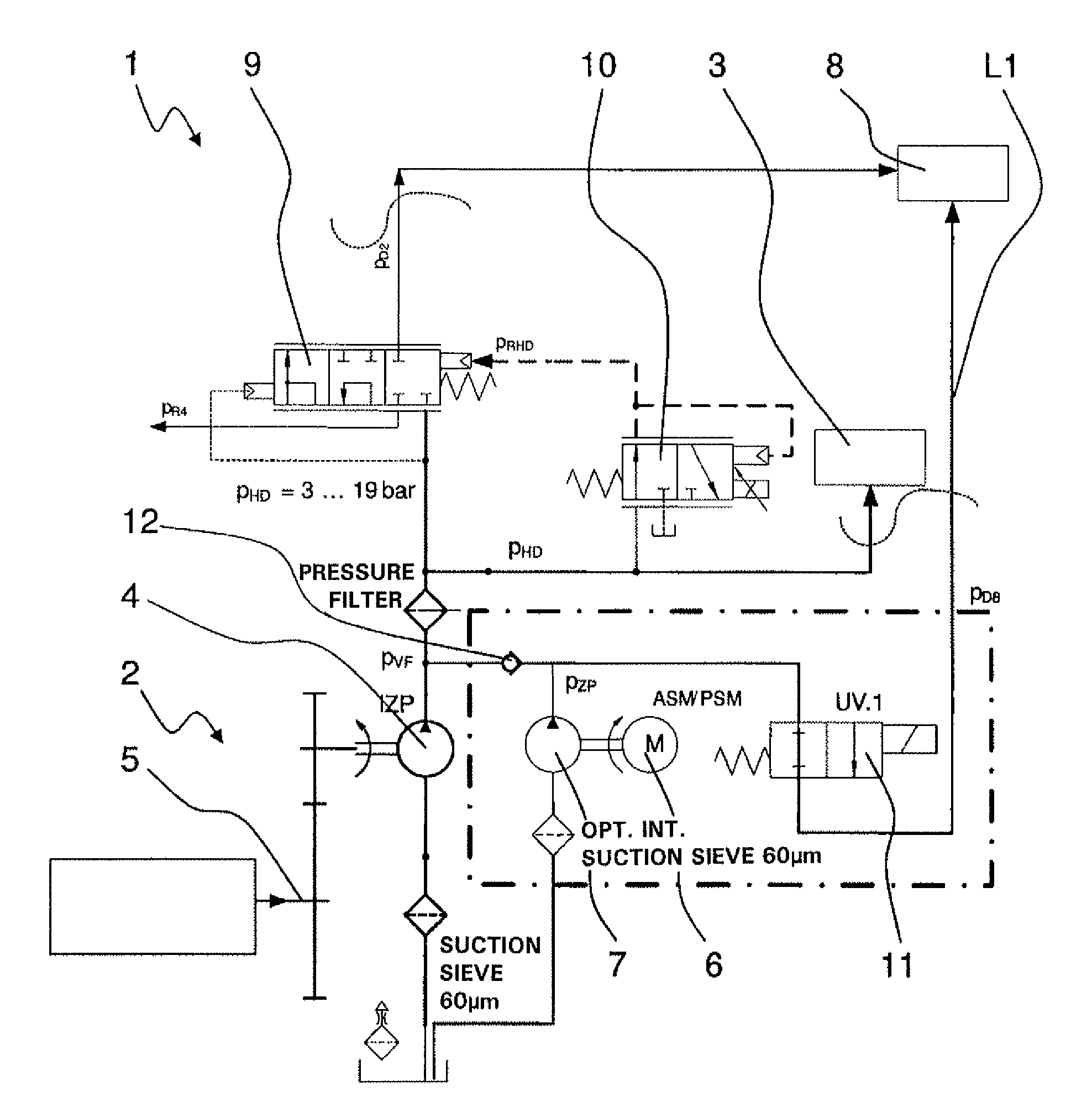
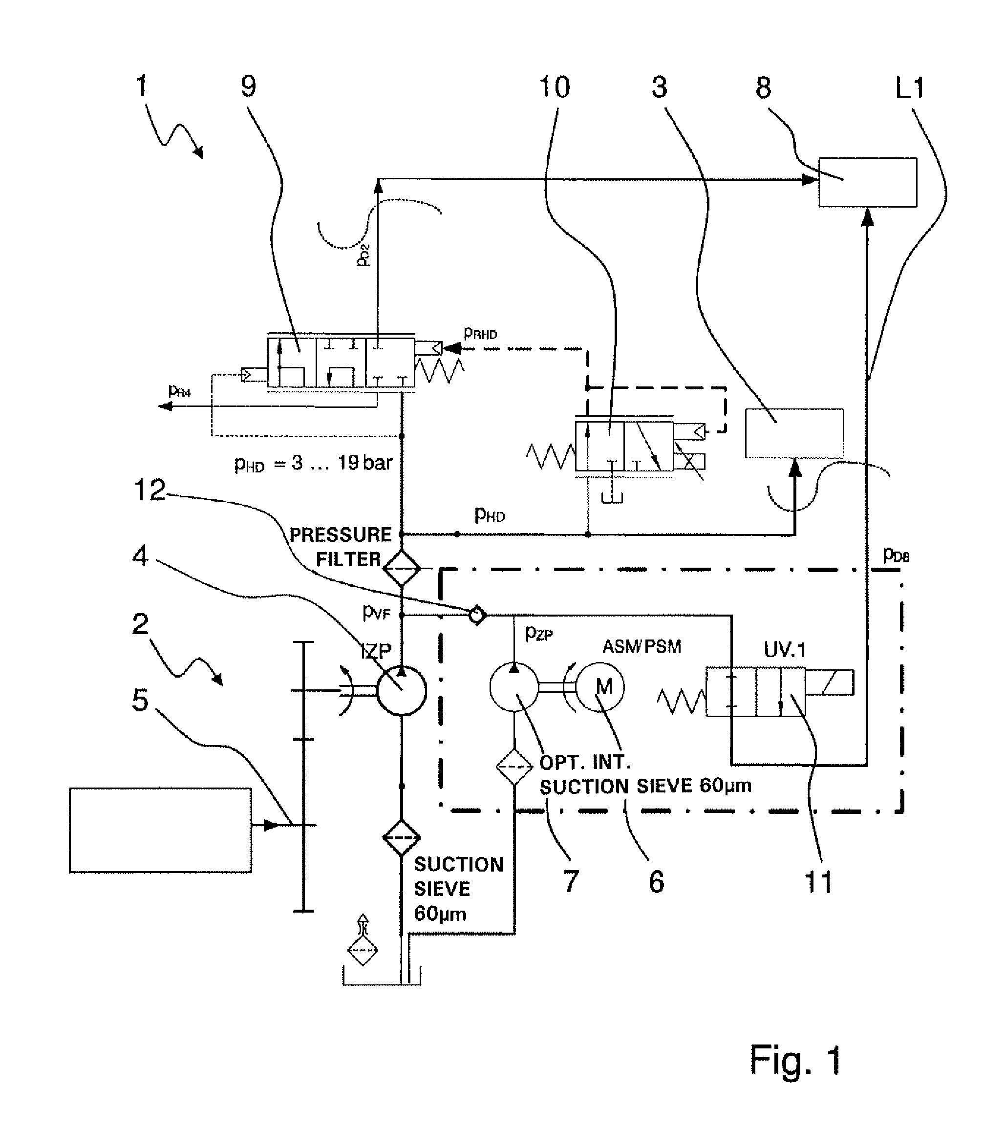
[0032]FIG. 1 shows a very schematic representation of a hydraulic system 1 of a transmission unit of a vehicle or a vehicle drivetrain, which is constructed with a hybrid drive in a manner known per se. The hybrid drive comprises a drive assembly in the form of an internal combustion engine, an electric machine 6 and a transmission unit 2. the transmission unit 2 can basically be any automated manual-shift transmission or automatic transmission known from the prior art, which is made with hydraulically actuated shift elements such as friction shifting clutches or disk brakes, and which can also be used in utility motor vehicles such as buses or the like.

[0033]In the transmission unit 2, a force flow can be produced by means of the shift elements that can be actuated hydraulically by the hydraulic system 1, the shift elements being supplied with an actuating pressure from a primary pressure circuit 3. Cooling and lubrication of the shift elements and other assemblies of the transmiss...


PUM


Abstract

A hydraulic system of a transmission comprises a main transmission pump that can be driven by torque transmitted via the transmission unit and with an auxiliary pump that can be driven by an electric machine, by which primary and secondary pressure circuits can be supplied with hydraulic fluid. Pressure sides of the main transmission pump and the auxiliary pump are connected to the primary pressure circuit upstream of a pressure relief valve provided for adjusting a main pressure in the primary pressure circuit. The pressure relief valve is arranged between the pressure sides of the main transmission pump and the auxiliary pump and the secondary pressure circuit. The pressure side of the auxiliary pump can be actively connected with the secondary pressure circuit, via a hydraulic line which can be blocked in the direction toward the primary and secondary pressure circuits, and which bypasses the pressure-relief valve.

Description

[0001]This application is a National Stage completion of PCT / EP2009 / 059166 filed Jul. 16, 2009, which claims priority from German patent application serial no. 10 2008 040 667.8 filed Jul. 24, 2008.FIELD OF THE INVENTION[0002]The invention concerns a hydraulic system of a transmission unit, comprising a main transmission pump and an auxiliary pump, and a method for operating such a hydraulic system.BACKGROUND OF THE INVENTION[0003]To be able to reduce both the fuel consumption and the pollutant emissions of vehicles made with internal combustion engines and known from practice, in various vehicle designs the internal combustion engine is switched off in appropriate operating states of the vehicle. Such functions are known, among other things, as engine start-stop functions and are activated or deactivated depending on the operating status of the most varied vehicle components, switching off the internal combustion engine even during short stops of the vehicle.[0004]To ensure that co...

Claims


Application Information

Patent Timeline
IPC IPC(8): F15D1/02
CPCF16H57/0446F16H2312/14F16H2061/0037F16H61/0031Y10T137/0396Y10T137/85978
Inventor BORNTRAEGER, KAIHUNOLD, BERNARDBACHMANN, MAXBUDACH, RENE
Owner ZF FRIEDRICHSHAFEN AG
Why Eureka
Try Eureka