Liquid metal thermal storage system

a thermal storage system and metal technology, applied in the direction of indirect heat exchangers, solar heat storage, lighting and heating apparatus, etc., can solve the problems of storing high temperature gas as a realistic energy storage option, restricting the heat flow into and out of storage materials, and limiting the use of this type of latent heat storage system, etc., to achieve excellent heat transfer within the metal, reduce the conversion efficiency, and high thermal conductivity of metals

Inactive Publication Date: 2011-05-26
THERMAPHASE ENERGY
View PDF17 Cites 32 Cited by
  • Summary
  • Abstract
  • Description
  • Claims
  • Application Information

AI Technical Summary

Benefits of technology

[0018]There are several advantages to this form of latent heat storage. First, most of the heat is released at a constant temperature which allows a gas turbine to operate at its design point. This is a consideration as off-design operation of gas turbines can significantly lower their conversion efficiency. Charging the thermal storage is accomplished by the gas at any reasonable temperature above the melting point of the metal. Because all suitable metals and alloys contract on melting there is no reason for metals to break their containing tubes or storage containers. The high thermal conductivity of the metal in both liquid and solid form provides excellent heat transfer within the metal. This avoids problems encountered in using liquid salts or alkali metals wherein low conductivity regions of the solid and solidifying material slow the release of heat.

Problems solved by technology

In latent heat storage systems using high temperature salts, there are restrictions in the heat flow into and out of the storage material due to the low conductivity of salt.
Thus the combination of the low conductivity of the salt and the curtailment of convection due to the immobility of the salt presents obstacles to the utilization of this type of latent heat storage system.
Oils break down at temperatures above about 400° C. Most thermal storage systems using salt operate below about 570° C. No effective means have been found to store steam at the pressures and temperatures required to run efficient Rankin cycle engines.
Storing high temperature gas is not a realistic energy storage option.

Method used


Image

  • Liquid metal thermal storage system
  • Liquid metal thermal storage system
  • Liquid metal thermal storage system

Examples


Embodiment Construction

[0030]The embodiments of the invention are illustrated in the context of a Brayton cycle solar thermal electric power plant. The skilled artisan will readily appreciate, however that the materials and methods disclosed herein will have application in a number of other contexts where high temperature thermal storage is desirable.

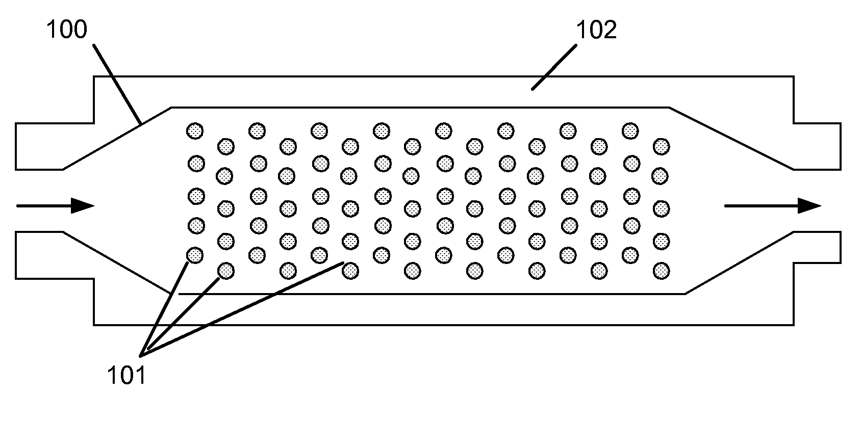
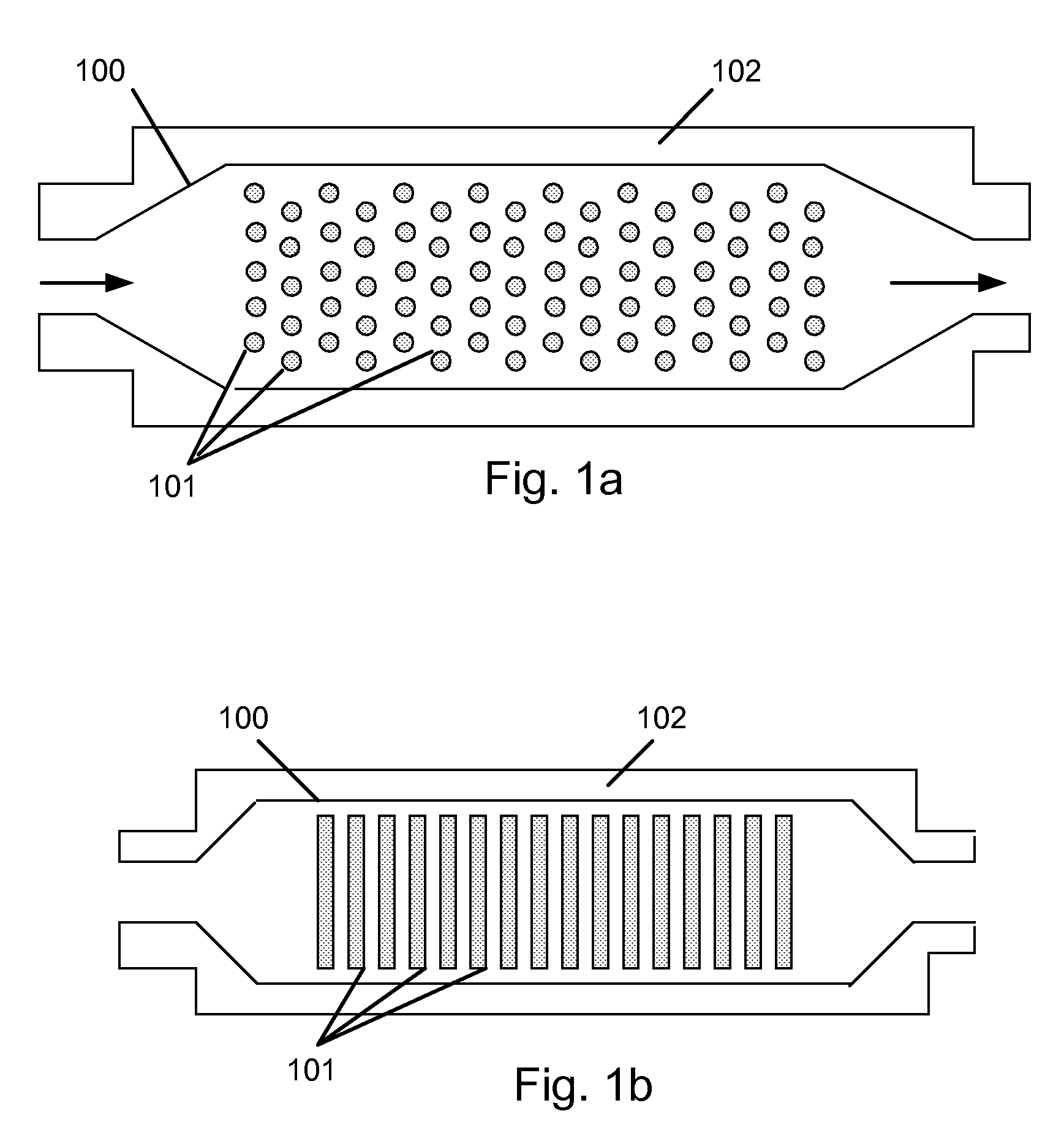
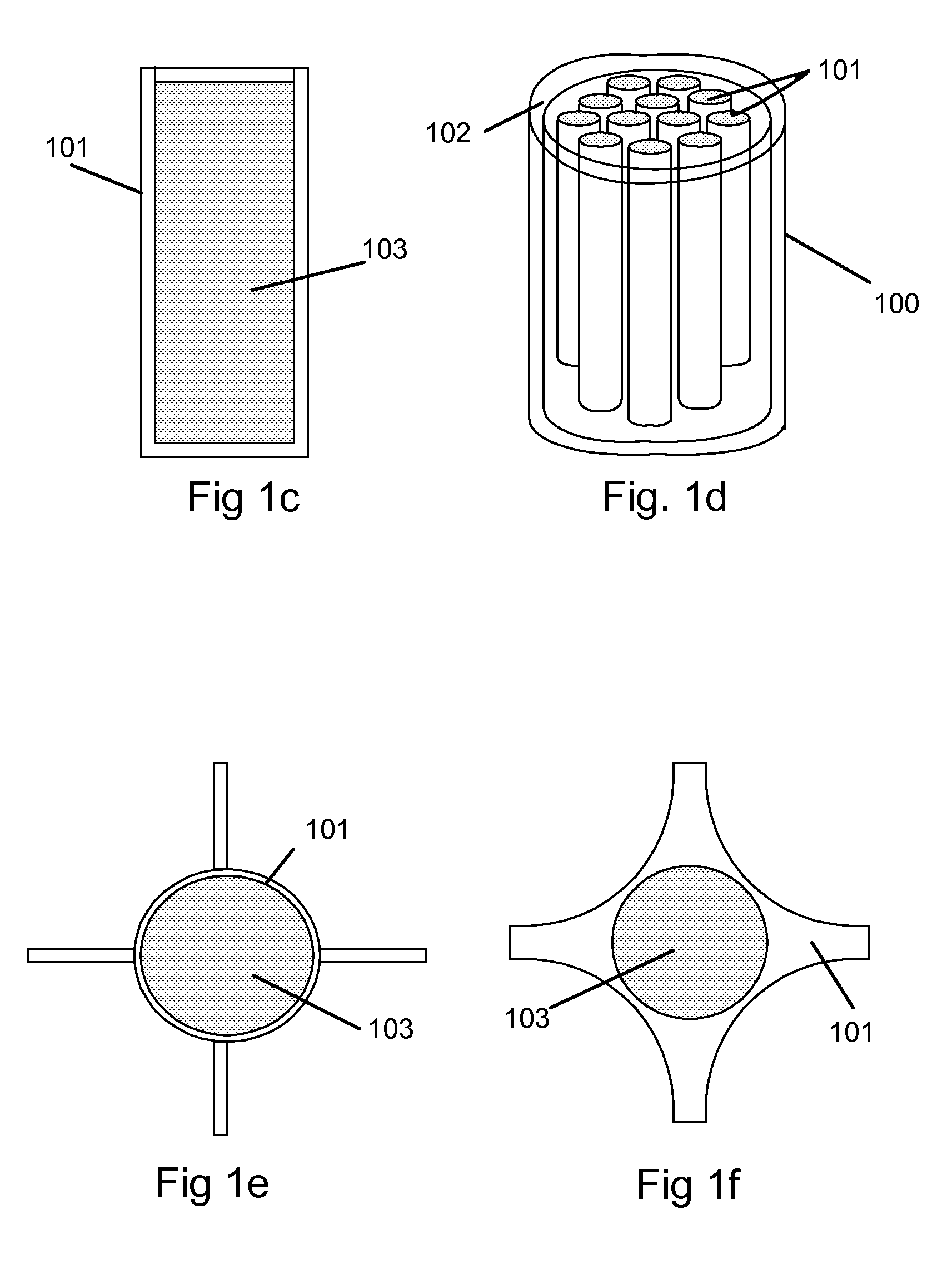
[0031]One embodiment of the invention, also know as a Liquid Metal Thermal Storage system (LIMETS) consists of substantially four items ; the metal or metal alloy thermal storage material, the tubes or a compartment containing the metal or metal alloy, the insulated cavity enclosing the tubes, and the heat transfer medium (gas). FIG. 1a is a top view of a schematic drawing of the system showing the insulated cavity 100, the ceramic or clad graphite tubes 101 containing the metal or metal alloy and the insulated container 102. FIG. 1b is a side view of the same components. FIG. 1c is a cross sectional view of the tube and metal showing one tube 101 and metal 1...


PUM

PropertyMeasurementUnit
temperatureaaaaaaaaaa
melting temperatureaaaaaaaaaa

Abstract

Embodiments of this invention relate generally to high temperature thermal energy storage, and more specifically, to the use of the latent heat of fusion of melting and solidifying metals to receive from and provide heat to a gaseous medium. Embodiments of this invention are also known as the Liquid Metal Thermal Storage system or LIMETS. Also described are methods of containing the storage material, heat transfer means, and choices of metals and alloys for thermal storage materials.

Description

CLAIM OF PRIORITY[0001]This application claims benefit of U.S. Provisional Application No. 61 / 276,269, filed Sep. 10, 2009, which is incorporated herein by reference in its entirety.BACKGROUND OF THE INVENTION[0002]The use of solar thermal power for generating electricity on a utility scale is having a resurgence of interest in light of global warming issues caused largely by the release of carbon dioxide, methane, and absorbing particulates in the atmosphere and to the increasing of fossil fuels. The use of concentrated solar energy to heat a working fluid to a high temperature to operate Rankin, Brayton, and Sterling cycle engines to provide mechanical power to operate a generator for utility scale electric power production offers an attractive alternative to the use of fossil fuels. However, utilities are generally requesting that power production facilities provide dispachable power on the order of 75% of the year. Since the sun is only above the horizon 50% of the time on a yea...

Claims


Application Information

Patent Timeline
Patent Type & Authority Applications(United States)
IPC IPC(8): F28F9/00F28D15/00
CPCF24J2/07F24J2/34F28D20/02F28D20/021Y02E60/145F28F21/04Y02E10/41Y02E10/46F28F21/02F24S20/20F24S60/00F24S60/10F24S60/30Y02P90/50Y02E60/14Y02E10/40
Inventor HUNT, ARLON J.
Owner THERMAPHASE ENERGY
Why Eureka
Try Eureka