Quad cable

a quadrangle and cable technology, applied in the field of cables, can solve the problems of water entering the cable, the use of electrical cables in marine environments is known to be problematic, and the inability to disclose the means, so as to achieve the effect of greatly improving the electrical properties of the signal carrying cabl

Inactive Publication Date: 2011-05-26
GORE ENTERPRISE HLDG INC
View PDF19 Cites 11 Cited by
  • Summary
  • Abstract
  • Description
  • Claims
  • Application Information

AI Technical Summary

Benefits of technology

[0024]The cable of the invention can be incorporated in a streamer for use in seismic surveys. Such streamers need to be flushable, i.e. the oil within the streamer can be flushed out of the interior of the streamer if required. Since—

Problems solved by technology

This application does not disclose the means by which the signal conductors or earth wires are held in place about the core.
The use of electrical cables in marine environments is known to be problematic since there is a risk that water may penetrate into the cable in the event of a cut or breach in the outer jacket.
One known disadvantage of the use of these materials is that the dielectric constant of the cable is changed by the addition of these materials in the cable.
Furthermore, as the conductors move within the cable, the relative posit

Method used


Image

  • Quad cable
  • Quad cable
  • Quad cable

Examples


example 1

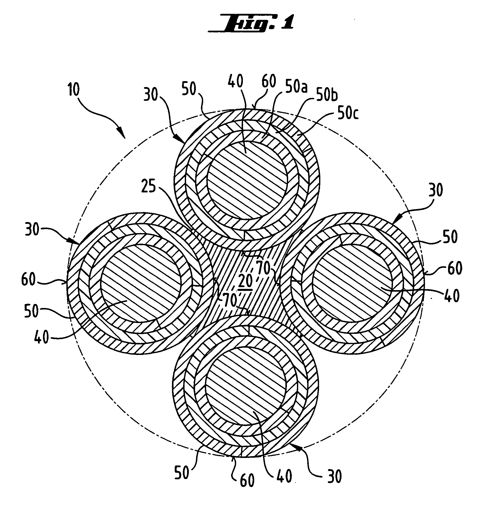
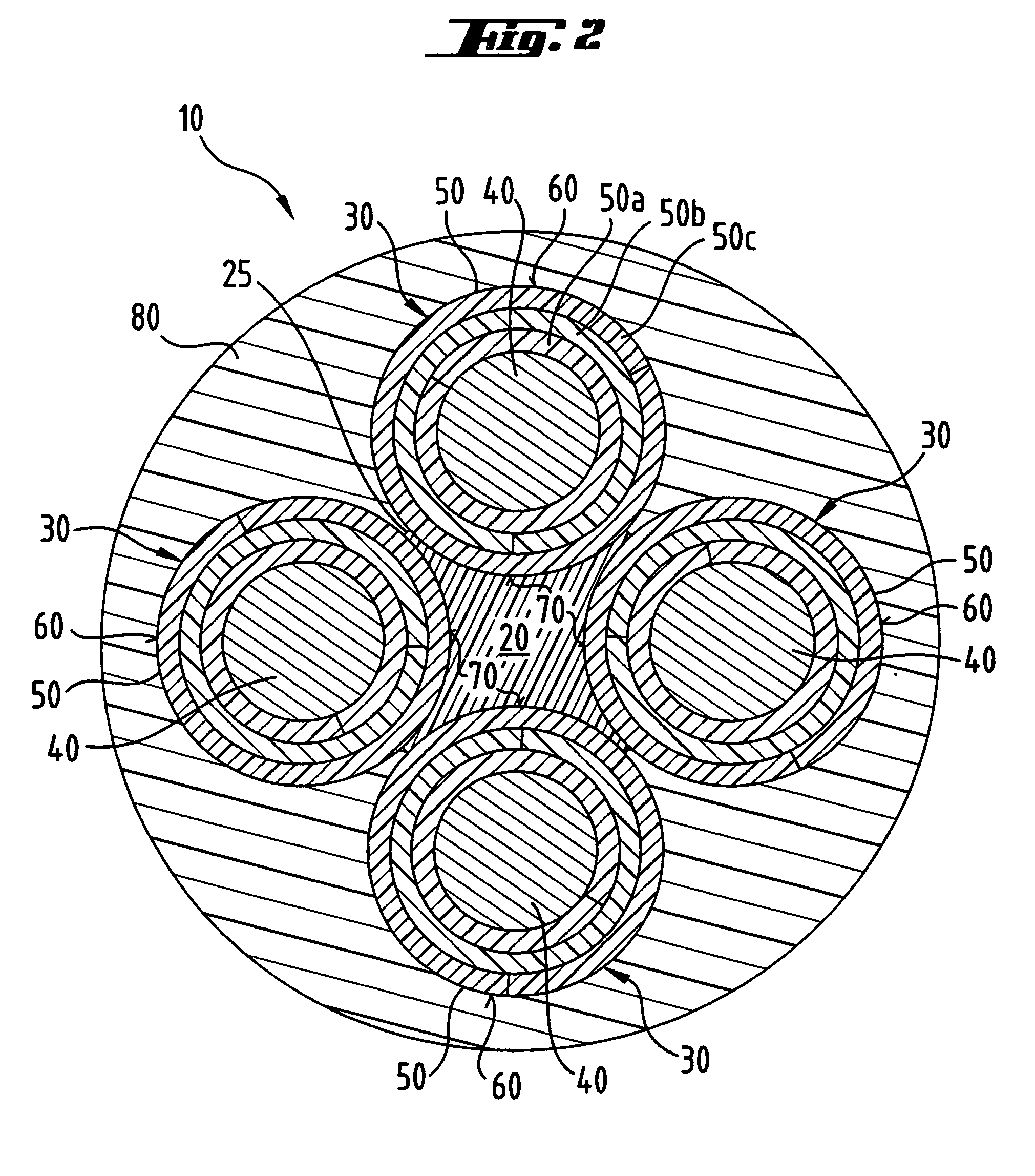
[0039]This cable 10 has the construction as shown in FIG. 1. The elongate core 20 is made of a 2.0 mm diameter ePTFE core.

[0040]Each of the four elongate elements 30 is made of an inner conductor 40 of silver plate copper of size AWG 2019 surrounded by an insulating layer 50 which comprises three layers 50a, 50b, 50c of tapes wrapped about the inner conductor 40. The first tape 50a is made of ePTFE and has a thickness of 101.6 μm. The second tape 50b is wound over the first tape 50a and the third tape 50c is wound over the second tape 50b. The second tape 50b and the third tape 50c are both made of full density PTFE and have a thickness of 101.6 μm and 76.2 μm respectively. The elongate elements 30 have a lay length of 38 mm. Prior to sintering the elongate elements 30 have a nominal outside diameter of 2.23 mm.

[0041]The elongate core 20 with the elongate elements 30 is passed at a maximum speed of 1.0 m per minute through the sintering oven 100 at 395° C. which results in a dwell t...

example 2

[0042]This has the same construction and is made in the same way as the cable 10 of Example 1. The elongate elements 30 are made of an inner conductor 40 of size AWG 2219 about which is wrapped a single tape of ePTFE of 0.9 mm thickness. The elongate core 30 is made of ePTFE and has a nominal outside diameter prior to sintering of 0.9 mm.

example 3

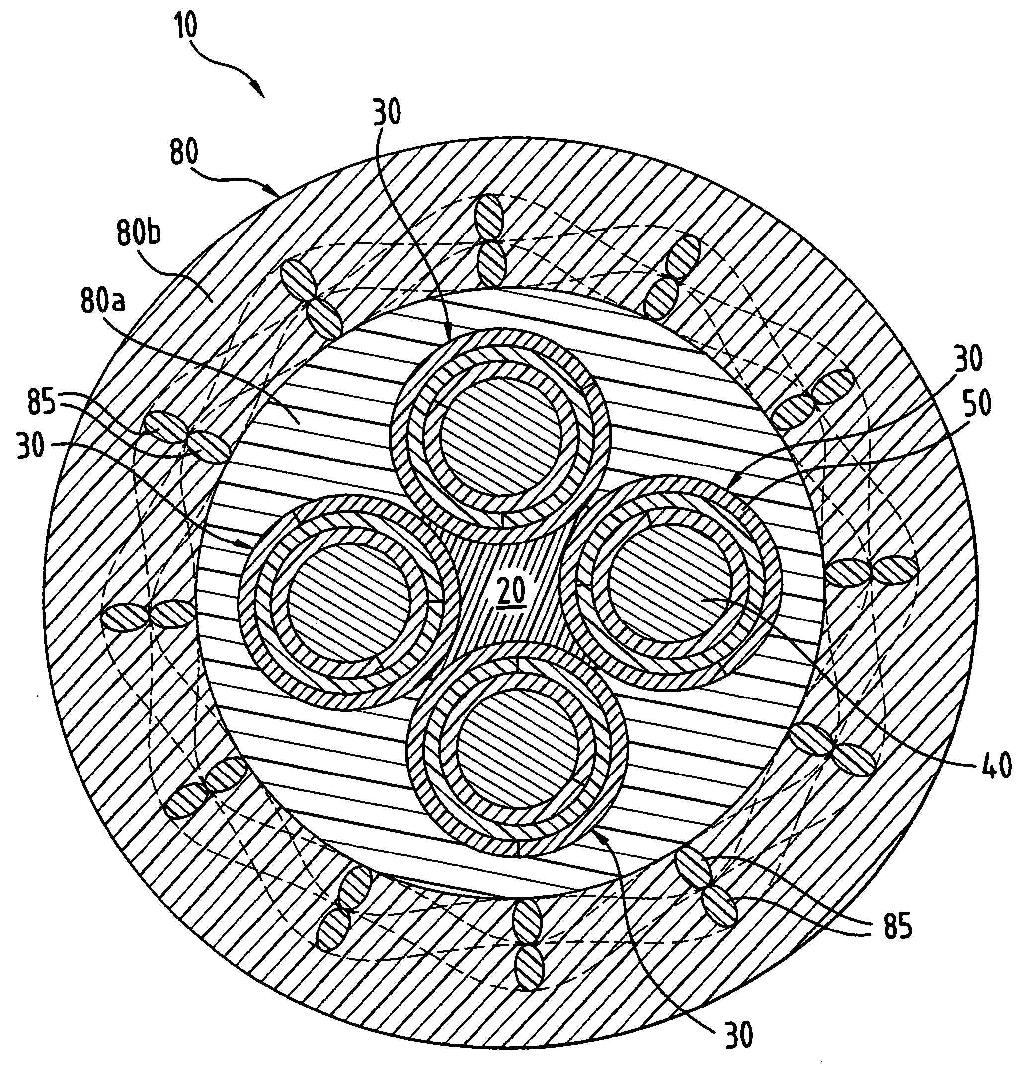
[0043]The construction of Example 3 is shown in FIG. 5. The quad cable 10 of Example 1 was provided additionally with a jacket 80. In this example, the jacket 80 comprised an inner jacket 80a and an outer jacket 80b, both of which were made of polyurethane. A braid 85 of a synthetic fiber, for example Technora, impregnated with PTFE was braided about the inner jacket 80a after extrusion of the inner jacket 80a and prior to extrusion of the outer jacket 80b. The braided synthetic fibre acts as a strength member.


PUM


Abstract

The invention relates to a cable (10) having an elongate core (20) made of a first dielectric material and having a core outer surface (25); and a plurality of elongate conducting elements (30) arranged about the elongate core (20). The elongate conducting elements (30) have an inner conductor (40) surrounded by an insulating layer (50) which is made of a second dielectric material. The outer surface of the inner conductor (40) is divided into a first outer surface area (60) and a second outer surface are a (70) and the first outer surface area (60) is attached, for example by sintering, to the core outer surface (25). The first and second dielectric materials are preferably expanded PTFE. The cable (10) finds application in a streamer (100) for use in seismographic surveys of the ocean bottom sub surface.

Description

FIELD OF THE INVENTION[0001]The invention relates to a cable having a core to which are attached a plurality of elongate conducting elements. In particular four conducting elements are used to form a quad cable.BACKGROUND OF THE INVENTION[0002]Quad cables are known in the art, for example U.S. Pat. No. 5,521,333 (Kobayawshi et al.) assigned to Sumitomo Electric Industries, Ltd., teaches a transmission cable including four insulated electric wires with a low dielectric central interposition member or elongate core. In the quad cable of this patent the elongate core is preferably made of polyethylene. The insulation of the insulated electric wires are also preferably made from polyethylene. A jacket of polyvinylchloride is disposed about the insulated wires. The insulated electric wires of this patent are held in place about the elongate core by means of polyester tape wound about the wires.[0003]Quad cables incorporating an elongate core or filler made from expanded polytetrafluoroet...

Claims


Application Information

Patent Timeline
IPC IPC(8): H01B7/00H01B13/00G01V1/20G02B6/44
CPCG01V1/201H01B7/046G02B6/4479G02B6/443
Inventor BOOTH, DAVID THOMASSMITH, JOHN DAVID
Owner GORE ENTERPRISE HLDG INC
Why Eureka
Try Eureka