X-ray window with beryllium support structure

a support structure and x-ray window technology, applied in the direction of optical radiation measurement, instruments, nuclear engineering, etc., can solve the problems of contamination lines, low atomic number contamination, and many support structures that interfere with the passage of radiation through the sheet of material, and achieve low x-ray spectra contamination, good effect, and high strength

Inactive Publication Date: 2011-05-26
MOXTEK INC
View PDF101 Cites 22 Cited by
  • Summary
  • Abstract
  • Description
  • Claims
  • Application Information

AI Technical Summary

Benefits of technology

[0009]Accordingly, it has been recognized that it would be advantageous to develop a radiation detection system having a high strength, yet thin, radiation detection window that has the desirable characteristics of good x-ray transmission and minimal x-ray spectra contamination. It has been recognized that it would be advantageous to develop a radiation detection system in which the CTE of the window support structure is closely matched to the CTE of the window mount in order to avoid thermal stresses in the window system as it is raised to higher temperatures. It has also been recognized that it would be advantageous to develop a radiation detection system which is not temperature limited by the adhesive, such as an epoxy, between the window mount and the support structure.

Problems solved by technology

While useful for providing support to an often thin and fragile sheet of material, many support structures are known to interfere with the passage of radiation through the sheet of material due to the structure's geometry, thickness and / or composition.
Unfortunately, x-ray windows, including the window support structure, can also fluoresce and thus emit x-rays that can cause contamination lines in the x-ray spectra.
Contamination from structures with an atomic number as low as 6, however, is still problematic.
Stresses in the support structure can result from raising the temperature due to a mismatch of the coefficient of thermal expansion (CTE) between the support structure and a window mount.
Due to these stresses, and the inherently brittle characteristic of silicon and diamond, cracks may develop in the support structure, thus weakening the support structure.
Some adhesives can have an upper temperature limit that can also result in window failure if the window is raised to a higher temperature.
Thus a CTE mismatch between the support structure and the window mount and / or adhesive temperature limitations can result in an upper temperature limit for the window.

Method used


Image

  • X-ray window with beryllium support structure
  • X-ray window with beryllium support structure
  • X-ray window with beryllium support structure

Examples


Embodiment Construction

[0020]Reference will now be made to the exemplary embodiments illustrated in the drawings, and specific language will be used herein to describe the same. It will nevertheless be understood that no limitation of the scope of the invention is thereby intended. Alterations and further modifications of the inventive features illustrated herein, and additional applications of the principles of the inventions as illustrated herein, which would occur to one skilled in the relevant art and having possession of this disclosure, are to be considered within the scope of the invention.

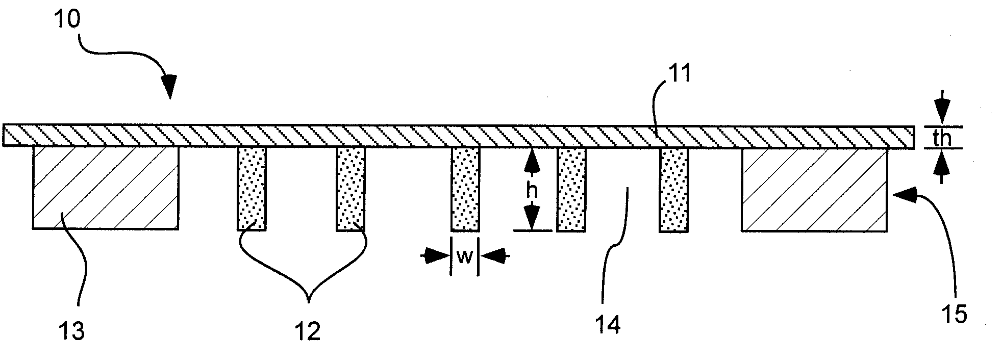
[0021]Shown in FIG. 1 is an x-ray window 10. The window includes a support structure which is comprised of a plurality of ribs 12 comprising beryllium, openings 14 between the plurality of ribs, and a support frame 13 around a perimeter of the ribs and carrying the ribs. The tops of the ribs terminate generally in a common plane. The window also includes a layer of thin film material 11 disposed over and spanning...


PUM


Abstract

A high strength window for a radiation detection system has a plurality of ribs comprising beryllium material. There are openings between the plurality of ribs. The tops of the ribs terminate generally in a common plane. The high strength window also has a support frame around a perimeter of the ribs. A layer of thin polymer film material is disposed over and spans the plurality of ribs and openings to pass radiation therethrough. A radiation detection system comprises a high strength window as described above and a sensor behind the window. The sensor is configured to detect radiation that passes through the window.

Description

CLAIM OF PRIORITY[0001]This is a continuation-in-part of U.S. patent application Ser. No. 11 / 756,946, filed on Jun. 1, 2007; which is hereby incorporated herein by reference in its entirety.FIELD OF THE INVENTION[0002]The present invention relates generally to radiation detection systems and associated high strength radiation detection windows.BACKGROUND[0003]Radiation detection systems are used in connection with detecting and sensing emitted radiation. Such systems can be used in connection with electron microscopy, X-ray telescopy, and X-ray spectroscopy. Radiation detection systems typically include in their structure a radiation detection window, which can pass radiation emitted from the radiation source to a radiation detector or sensor, and can also filter or block undesired radiation.[0004]Standard radiation detection windows typically comprise a sheet of material, which is placed over an opening or entrance to the detector. As a general rule, the thickness of the sheet of m...

Claims


Application Information

Patent Timeline
Patent Type & Authority Applications(United States)
IPC IPC(8): H01J5/18G01J1/00
CPCH01J5/18H01J37/244H01J2237/2445H01J2235/18H01J47/004
Inventor LIDDIARD, STEVEN D.DECKER, KEITH W.XU, DEGAO
Owner MOXTEK INC
Why Eureka
Try Eureka