
Power transistor driving circuits and methods for switching mode power supplies

a power transistor and driving circuit technology, applied in the direction of process and machine control, pulse technique, instruments, etc., can solve the problems of greater noise, electromagnetic interference at the switching frequency or harmonic of the power transistor, output performance limitations in the switched mode power supply, etc., to reduce switching loss, wide range of applicability, and improve conversion efficiency

Active Publication Date: 2011-05-26
BCD SHANGHAI MICRO ELECTRONICS CO LTD
View PDF4 Cites 20 Cited by
  • Summary
  • Abstract
  • Description
  • Claims
  • Application Information

AI Technical Summary

Benefits of technology

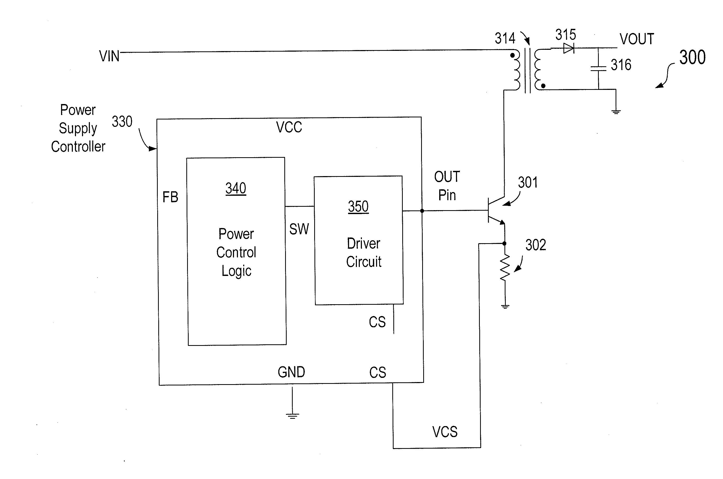
[0010]Embodiments of the present invention provides methods and circuits for controlling a power transistor in a switching mode power supply (SMPS). In a specific embodiment, a method and circuits is provided for multi-stage turn on and turn off the power transistor to achieve reduced switching loss and better conversion efficiency. But it would be recognized that the invention has a much broader range of applicability.
[0016]In some embodiments, when it is time to cut off the remaining forward driving current, the power transistor turn off stage starts with the discharge of storage charges rapidly by overdriving a discharge transistor coupled to the power transistor. And after the initial discharge of the storage charge, a moderate Rdson of the discharge transistor is maintained. In this way, a large reverse current is generated to provide a rapid turn-off of the power transistor. As a result, lower switching loss is achieved. More details of these embodiments are described below in the context of a bipolar power transistor.
[0017]In another embodiment, a method is provided for short circuit protection of the power supply, which could be damaged if the current sensing circuit on the primary side malfunctions. For example, if the current sense resistor is shorted or is changed to a lower value, a large current may flow in the power supply circuit. In embodiments of the invention, with the multistage turn-on methods, the power transistor is only turned on by the initial overdrive current. And virtually no further base drive current is generated due to the lower voltage on the current sense resistor, so the power transistor will turn on for a short period of time and then be cut off. In this embodiment, the primary current is prevented from continuing to increase indefinitely, thus ensuring the safety of the power transistor and the whole system. This method is more reliable and efficient compared with conventional driving methods.

Problems solved by technology

On the other hand, they also have the disadvantages of greater noise, especially Electromagnetic Interference at the power transistor's switching frequency or its harmonics.
The effect of these components often are difficulty to determine in advance and can lead to output performance limitations in the switched mode power supply.

Method used


Image

  • Power transistor driving circuits and methods for switching mode power supplies
  • Power transistor driving circuits and methods for switching mode power supplies
  • Power transistor driving circuits and methods for switching mode power supplies

Examples


Embodiment Construction

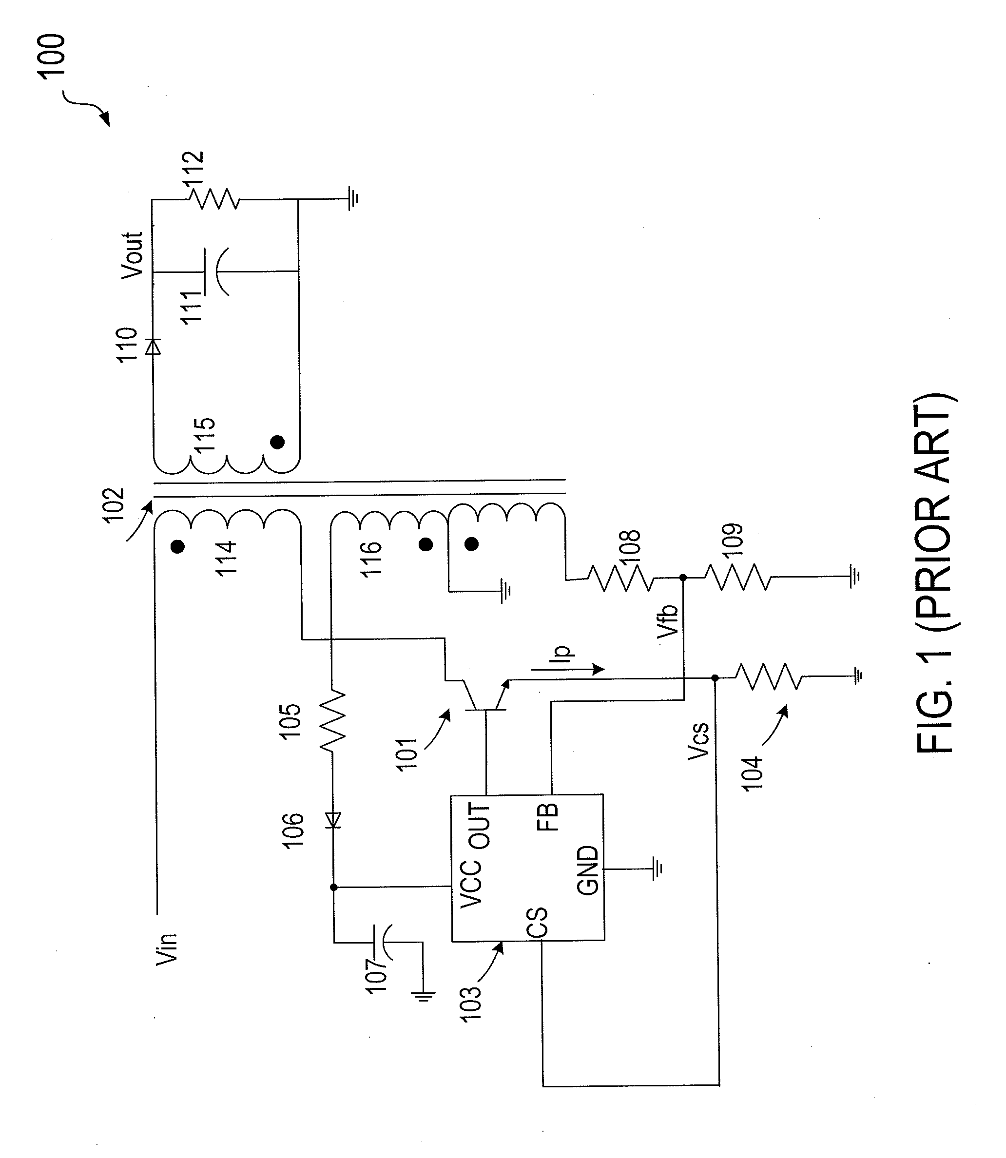
[0033]FIG. 1 is a schematic diagram illustrating a conventional switching mode power supply system (SMPS) 100. As shown, SMPS 100 is a flyback-type primary side regulated switched mode power supply using a pulse frequency modulation (PFM) control. The primary side regulated switched mode power supply includes a rectifier and capacitor (not shown) that converts an AC mains voltage to an unregulated voltage Vin, which is then applied to a terminal of a primary winding 114 of a transformer 102. Primary winding 114 is also coupled to a high voltage NPN power transistor 101, which is turned on and off by a signal OUT of a power supply controller 103. When transistor 101 is turned on, a primary current Ip flows through primary winding 114, which starts to build up a magnetic energy. A secondary winding 115 is magnetically coupled to primary winding 114. When transistor 101 is turned on, the magnetic field produced by a primary current Ip induces a voltage in secondary winding 115. When tr...


PUM


Abstract

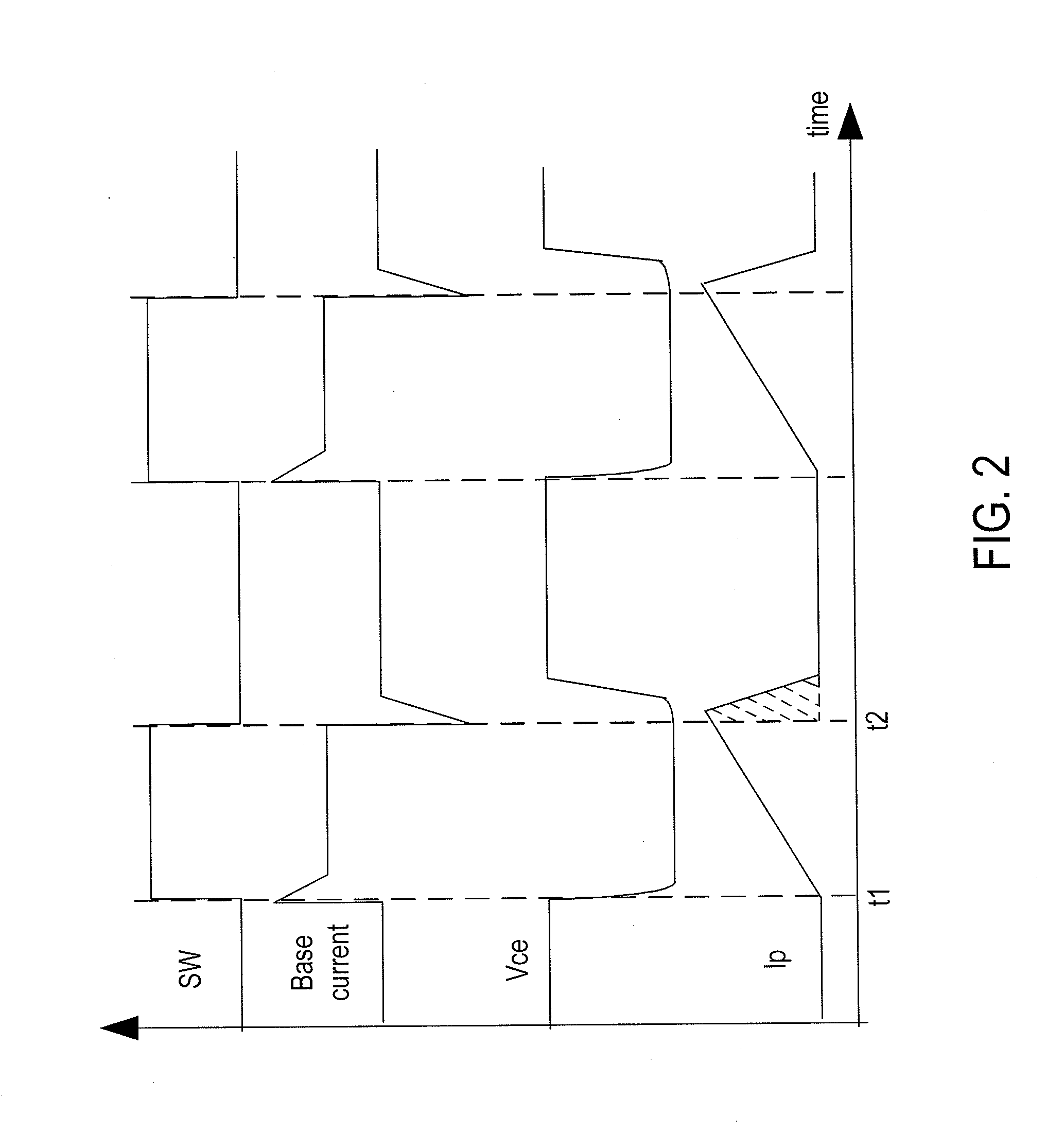
A power supply controller is provided for providing a drive current to a control terminal of a power transistor in three time intervals. The controller includes control circuits configured to control the drive current in multiple stages. During a first time interval, first drive current includes a current spike for turning on the power transistor in response to a start of the control signal pulse. During a second time interval, a second drive current includes a ramping current substantially proportional to a magnitude of a current through the power transistor. During a third time interval, current flow to the power transistor is at least partially turned off before an end of the control signal pulse.

Description

CROSS-REFERENCES TO RELATED APPLICATIONS[0001]This application claims priority to Chinese Patent Application No. 200910226104.3, filed Nov. 20, 2009 by inventors Jianhua Duan et. al., commonly assigned and incorporated in its entirety by reference herein for all purposes.BACKGROUND OF THE INVENTION[0002]Embodiments of the present invention are directed to power supply control circuits and power supply systems. More particularly, embodiments of the present invention provides methods and circuits for controlling a power transistor in a switching mode power supply (SMPS).[0003]Regulated power supplies are indispensable in modern electronics. For example, the power supply in a personal computer often needs to receive power input from various outlets. Desktop and laptop computers often have regulated power supplies on the motherboard to supply power to the CPU, memories, and periphery circuitry. Regulated power supplies are also used in a wide variety of applications, such as home applia...

Claims


Application Information

Patent Timeline
IPC IPC(8): H02M3/335G05F1/10
CPCH02M3/33507H03K17/16H03K2217/0036H03K17/04123G05F3/26G05F3/267G05F3/30
Inventor DUAN, JIANHUAZONG, QIANGZHU, YAJIANG
Owner BCD SHANGHAI MICRO ELECTRONICS CO LTD
Learn More