
Biochip detection system with image correction unit and distorted image correcting method using the same

Inactive Publication Date: 2011-06-02
KIM SOO KYUNG +3
View PDF10 Cites 1 Cited by
  • Summary
  • Abstract
  • Description
  • Claims
  • Application Information

AI Technical Summary

Benefits of technology

[0017]The present invention is directed to solving the problems of the related art, and an aspect of the present invention is to provide a biochip detection system with a rotatable stage, which can form a more accurate and reliable image by correcting distortion of bio-information images while simultaneously detecting biochip information of biochips in a rotation manner, thereby enhancing speed and reliability of detection.
[0018]In accordance with one aspect of the invention, a biochip detection system with a rotatable detection stage capable of loading at least one biochip thereon to detect information of the biochip by emitting light includes: a detector detecting and converting light reflected from the biochip into a detection signal; an image data unit converting the detection signal into image data; and an image correction unit correcting a distorted image of the detection signal, so that the distorted image detected on the high-speed rotatable detection stage for recognizing bio-information of the biochip can be corrected into an orthogonal image, thereby quickly acquiring more accurate and reliable bio-information.
[0021]where Xi is a range of a current row, Xo is a length of an ideal range scanned on the outer periphery, Ro is a radius to the outer periphery, and Ri is a radius of the current row. The image cutter can solve a problem that an overlap-scanning area increases and an image corresponding to the scanned section becomes elongated as it goes from the outer periphery to the inner periphery due to scanning at a constant angular velocity, thereby enabling the raw data to be cut in a scan range corresponding to an accurately required section.
[0024]The biochip detection system may further include a high-speed data processor for data-blocking, temporarily storing, and transmitting a digitalized detection signal to another host, thereby enhancing operation efficiency of the system.
[0028]In accordance with another aspect, a method of correcting an image detected by a rotatable biochip detection system includes: detecting an image of at least one biochip mounted on a rotatable stage as raw data in an optical pickup unit; cutting the raw data to be sorted corresponding to each biochip mounted on the rotatable stage; and converting rotary data of the sorted data of the biochip into an orthogonal array, thereby correcting distortion of a bio-information image detected in a rotational manner to acquire detection information with high reliability.
[0029]The detecting an image of at least one biochip may include cutting the image of the biochip by calculating a range of a region where bio-information of each biochip is scanned while being rotated in a unit of row, thereby efficiently catching the bio-information within an effective range.

Problems solved by technology

However, since such an optical detection method makes it difficult to reduce the size of the system thereof and does not provide digitized outputs, studies have been conducted into development of new detection methods capable of outputting results via electric signals.
However, this method has a drawback in that it also needs a separate labeling process.
Since a fluorescent signal emitted from the fluorochrome often becomes weak depending on detection conditions, environmental changes, etc., it is necessary for a biochip scanner based on the laser-induced fluorescence detection method to use a detector such as an expensive and sensitive PMT for sensing the fluorescent signal and many optical components for detecting a fixed degree, such as a dichronic filter, an emission filter, and the like, which cause an increase in manufacturing costs while complicating a detection condition to obstruct generalization of the scanner.
Thus, the conventional method is very inefficient since it takes considerable time to read out information for each biochip.
Thus, it is not only difficult to perform high-speed scanning but also impossible to scan a plurality of biochips.

Method used


Image

  • Biochip detection system with image correction unit and distorted image correcting method using the same
  • Biochip detection system with image correction unit and distorted image correcting method using the same
  • Biochip detection system with image correction unit and distorted image correcting method using the same

Examples


Embodiment Construction

[0042]A biochip scanner with a rotatable stage according to one embodiment of the invention will be described and a method of solving the problem will be proposed.

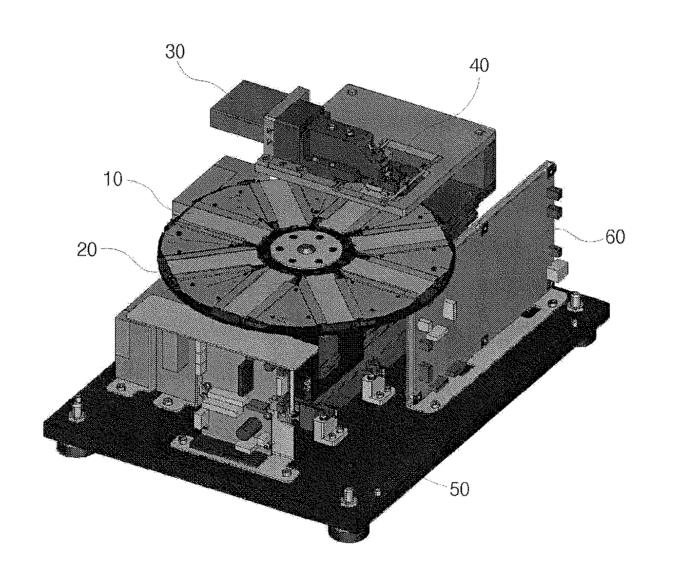
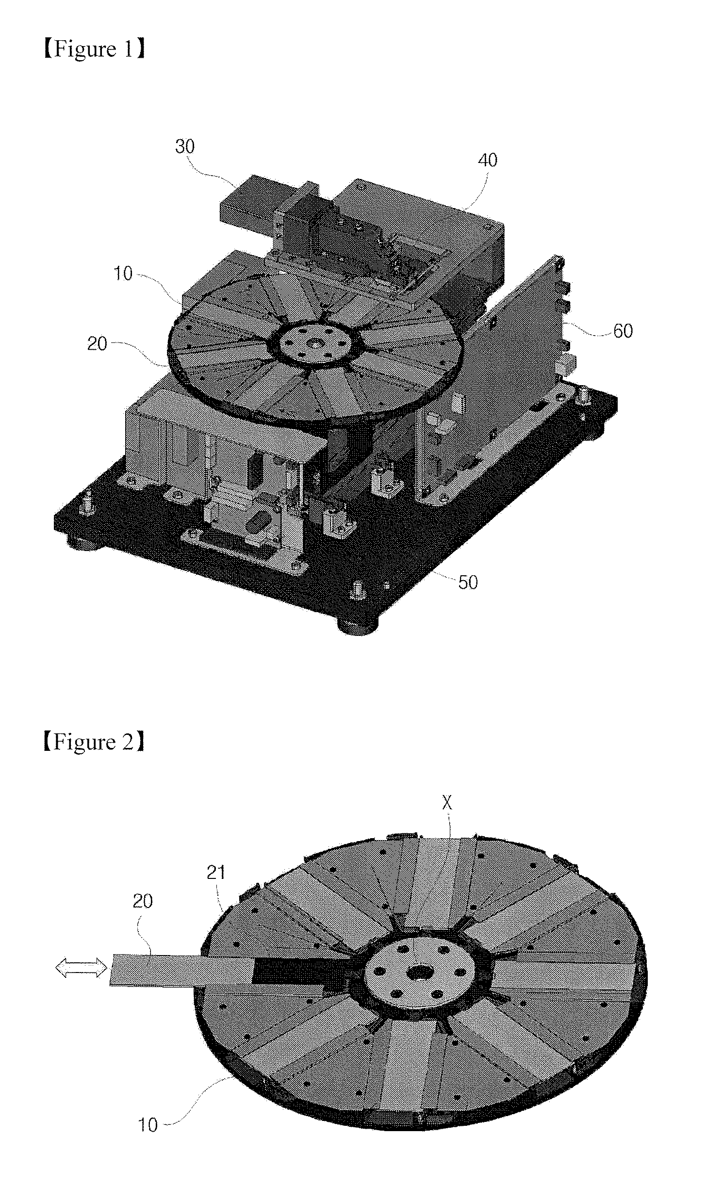
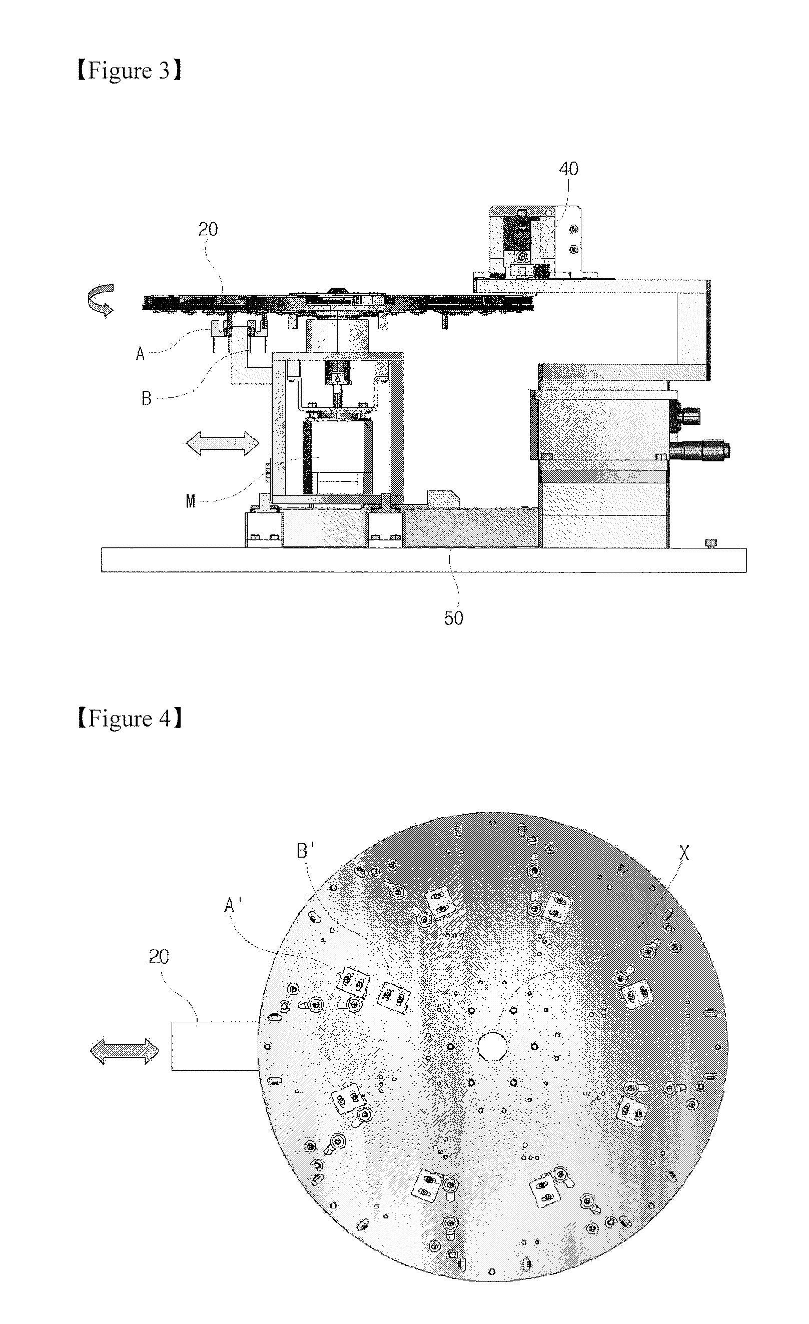
[0043]Referring to FIG. 1, a biochip scanner according to one embodiment of the invention includes a plate-shaped stage 10 that is capable of rotating at high speed and includes at least one biochip mounted thereon. When the stage 10 including the biochip is rotated at high speed, an optical pickup unit 40 emits light and an optical detector 30 detects bio-information based on the reflected light. For detection of the optical pickup 40 from the center of the stage 10, i.e., from a rotational center, the scanner is provided with a disc transfer motor 50 which transfers the stage 10. In the biochip detection system of the embodiment, a plurality of biochips are mounted on the detection stage rotating at high speed, so that information of the biochips can be simultaneously detected in a rotational manner, thereby enhancing de...


PUM


Abstract

The present disclosure relates to a biochip detection system capable of correcting a distorted part of detection data acquired by a detection stage rotated at high speed for detecting bio-information of the biochip, and a method of correcting the distorted image of the detection data using the same. The biochip detection system with a rotatable detection stage capable of loading at least one biochip thereon to detect information of the biochip by emitting light includes a detector detecting and converting light reflected from the biochip into a detection signal, an image data unit converting the detection signal into image data, and an image correction unit correcting a distorted image of the detection signal. The biochip detection system can correct an image, which is distorted during detection of the high-speed rotatable detection stage, into an orthogonal image, so that more accurate and reliable bio-information can be quickly acquired.

Description

BACKGROUND OF THE INVENTION[0001]1. Field of the Invention[0002]The present invention relates to a biochip detection scanner with a high-speed rotatable detection stage for detecting information about a biochip and, more particularly, to a biochip detection system and an image correcting method of the same, which is capable of quickly acquiring more accurate and reliable bio-information by correcting a distorted image, detected in a high-speed rotatable detection stage for recognizing bio-information about a biochip, into an orthogonal image.[0003]2. Description of the Related Art[0004]A biochip is a chip in which a probe for bio-molecules, such as deoxyribo nucleic acid (DNA), protein, and the like, is attached at high density to a substrate to analyze a gene expression pattern, a gene defect, a protein distribution, a reaction pattern, and the like in a sample. According to probe attachment types, the biochip is classified into a microarray chip where the probe is attached to a so...

Claims


Application Information

Patent Timeline
IPC IPC(8): G06K9/00
CPCG06T5/006G06T2207/30024G06T2207/10064G06T5/80
Inventor KIM, SOO KYUNGCHO, WON HYUNGKIM, IN GYUHEO, SEONG PIL
Owner KIM SOO KYUNG
Learn More