
Scribing wheel and method for scribing brittle material substrate

a brittle material and substrate technology, applied in the direction of paper/cardboard containers, manufacturing tools, transportation and packaging, etc., can solve the problems of inconsistency in the size of the pieces gained, lower yield, and inconsistent shrinkage rate, so as to achieve good scribing effect, long length of cut, and low cost

Inactive Publication Date: 2011-06-09
MITSUBOSHI DIAMOND IND CO LTD
View PDF21 Cites 15 Cited by
  • Summary
  • Abstract
  • Description
  • Claims
  • Application Information

AI Technical Summary

Benefits of technology

The present invention relates to a scribing wheel and a method for cutting ceramic substrates, particularly LTCC substrates, sapphire or silicon, through breaking. The technical effects of the invention include improving the ability of the scribing wheel to bite into ceramic substrates, creating vertical cracks that extend deep in the direction of the thickness of the substrate, and preventing horizontal cracking and chipping when scribing the substrate. These improvements lead to higher yields and better productivity in the manufacture of LTCC substrates.

Problems solved by technology

In addition, the rate of shrinkage is inconsistent throughout the green sheet.
Since grooves in V shape are created and the lines for cutting are set before burning, inconsistency in the rate of shrinkage causes inconsistency in the size of the pieces gained through cutting after burning, which results in a lower yield.
In addition, burning after the creation of grooves makes is easier for the substrate to be deformed during burning, and the cut surfaces become poor.
Furthermore, in the case where the substrate is thin, the green sheet with grooves before burning and the burned substrate before cutting may break unexpectedly along the grooves in V shape when transported, and thus there may be a risk of problems hindering transportation.
In this method, however, it is difficult to position the grooves.
However, dicing has the following problems: (1) the rate of cutting is generally as slow as 5 to 10 min / sec, making the tact time long and the productivity extremely low.
(2) Loss of material cannot be avoided due to the thickness of the dicing saw (kerf loss).
(4) It is necessary to use cooling and washing water, and therefore MQL (minimum quantity lubrication) is impossible though desirable since it is environmentally friendly, and substrates on which electronic parts are mounted cannot be diced.
(6) The quality of the cut surface is greatly affected by the diamond abrasive grains.
(7) The life of the blade is short, making the running cost high.
Though laser scribing is also possible, it has the following problems: (1) Marks remain on the cut surfaces as a result of perforation through pulse irradiation, which makes the quality lower.
(2) The process causes fumes due to the heat.
(4) The cost of the apparatus is high.
However, ceramic substrates are generally harder than glass substrates, and therefore cutting of a ceramic substrate through breaking has the following problems: (1) It is difficult for the scribing wheel to bite into ceramic substrates, and thus it is difficult to create a scribe line.
(2) Cracks created through scribing barely extend in the direction of the thickness of the substrate, and thus it is difficult for the cracks to run deep, making it difficult to break the substrate.
(3) When there are through holes in the ceramic substrate, it is difficult for the wheel to roll straight, and thus scribe lines are not created in predetermined locations, the amount of bite of the scribing wheel becomes inconsistent, and the life of the scribing wheel becomes shorter.
In addition, in order to cut a ceramic substrate for electronic parts through breaking with a high yield, multi-pass scribing is necessary, because vertical cracks created through scribing using a conventional scribing wheel are too shallow.
The scribing wheel of a deeper biting type in Patent Document 1 easily bites into glass substrates and fragile materials that are harder than glass (such as ceramic), and can create vertical cracks that run deep in the direction of the thickness of the substrate.
However, when a scribing wheel of a deeper biting type for glass substrates is used to cut a hard, fragile material, the blade 12 wears in a short period of time, and thus such use is not practical.
The scribing wheel in Patent Document 3 is also not sufficient in the depth of the vertical cracks and the life of the blade.

Method used


Image

  • Scribing wheel and method for scribing brittle material substrate
  • Scribing wheel and method for scribing brittle material substrate
  • Scribing wheel and method for scribing brittle material substrate

Examples


Embodiment Construction

[0051]In the following, the scribing wheel according to the present invention is described in detail, but the present invention is not limited to these embodiments.

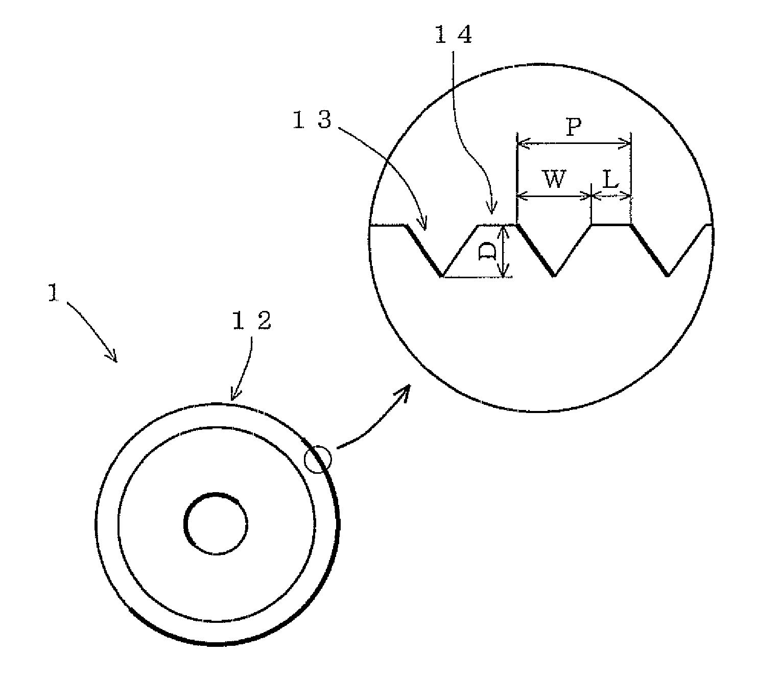
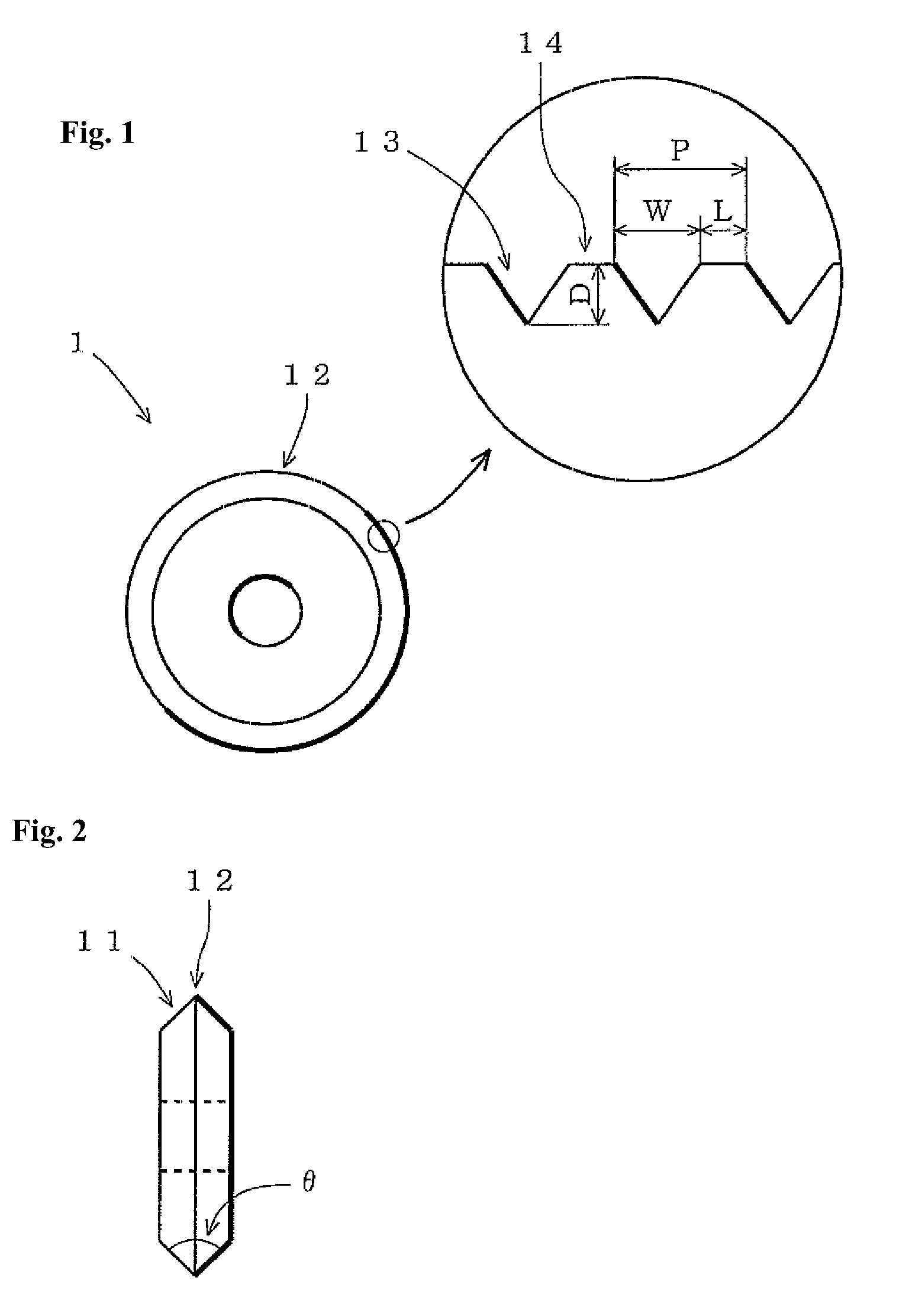
[0052]FIGS. 1 and 2 show the scribing wheel according to one embodiment of the present invention. FIG. 1 is a front diagram showing the scribing wheel as viewed in the direction of the rotational axis, and FIG. 2 is a side diagram. As shown in FIG. 2, a blade 11 in V shape is formed around the circumference of a wheel in disc form.

[0053]The angle θ of the edge of this blade 11 is usually obtuse, for example within a range of 90° to 160° (specifically, 100° to 140°), though an appropriate value can be set in accordance with the material and thickness of the substrate to be cut. As shown in FIG. 1, a number of grooves 13 in V shape are created at predetermined intervals in the edge 12 of the blade 11 along the ridgeline. Here, the number of grooves 13 in the blade edge 12 are designed in the order of micrometers, and differ...


PUM

PropertyMeasurementUnit
outer diameteraaaaaaaaaa
angleaaaaaaaaaa
depthaaaaaaaaaa

Abstract

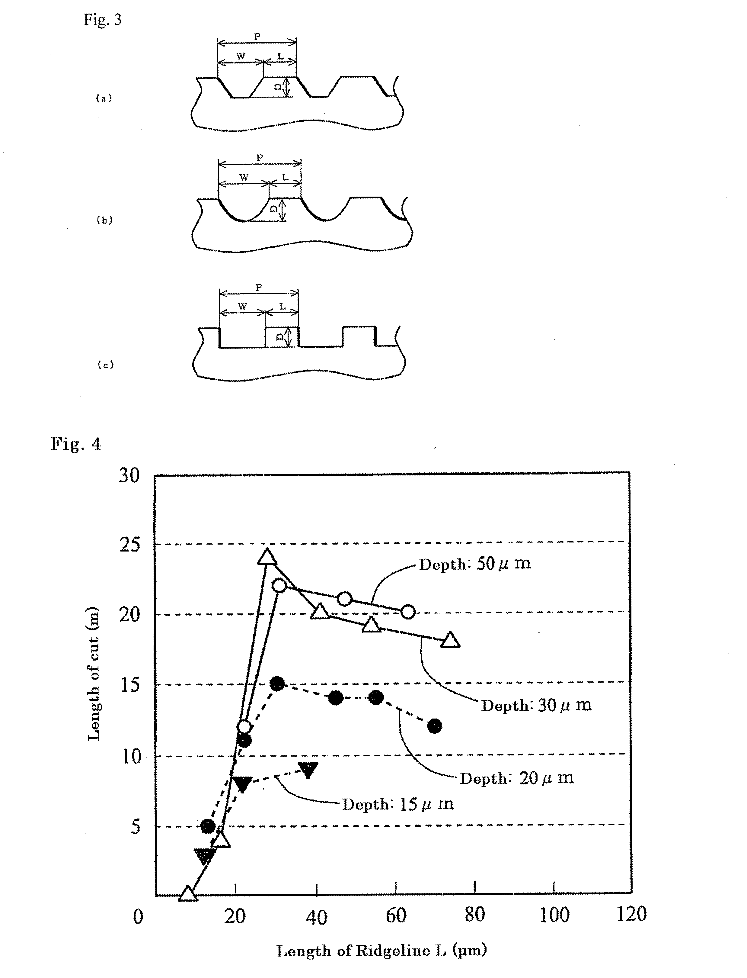
A scribing wheel having a long life with little wear at the blade even when used to scribe a substrate that is relatively hard, such as a ceramic substrate, which can create deep vertical cracks if necessary is provided. A number of grooves 13 are created with predetermined intervals at the blade 12 that is along the ridgeline of the wheel of which the outer diameter is within a range of 1 mm to 5 mm. The depth D of these grooves 13 is 25 μm or more and the length of the ridgeline 14 between grooves is 25 μm or more. It is preferable for the pitch P of the grooves 13 to be in a range from 50 μm to 200 μm.

Description

TECHNICAL FIELD[0001]The present invention relates to a scribing wheel which is appropriate for use for creating a scribe line on the surface of a brittle material substrate and a method for scribing a line on the surface of a brittle material substrate, and in particular to a scribing wheel which is appropriate for use for creating a scribe line on the surface of a brittle material that is harder than glass, for example a ceramic substrate (a substrate to be built in an electronic part, such as a multilayer substrate made of ceramic burned at a high temperature (HTCC substrate) and a multilayer substrate made of ceramic burned at a low temperature (LTCC substrate)), sapphire or silicon, as well as a scribing method.BACKGROUND ART[0002]In recent years LTCC substrates have been drawing attention as a means for making it possible to increase the density and reduce the size of a module, and in particular it is said that LTCC substrates are optimal for high frequency modules for communi...

Claims


Application Information

Patent Timeline
Patent Type & Authority Applications(United States)
IPC IPC(8): B28D5/00B26D3/08B26F3/00
CPCB28D1/24B28D1/225Y10T83/0341Y10T83/0385Y10T225/12B28D5/0011
Inventor TOMEI, MAOKOOKAMOTO, KEITAROTOMIMORI, HIROSHI
Owner MITSUBOSHI DIAMOND IND CO LTD
Learn More