Cathode design

Inactive Publication Date: 2011-06-09
NAT UNIV OF SINGAPORE
View PDF3 Cites 3 Cited by
  • Summary
  • Abstract
  • Description
  • Claims
  • Application Information

AI Technical Summary

Benefits of technology

An MFC according to one aspect of the invention provides a new type of cathode for single-chambered air-cathode MFC wherein the catalyst layer is applied to the side of the cathode exposed to the air on top of a backing layer. The catalyst layer can then be protected by one or more gas diffusion layers. By providing a catalyst layer that is facing the air, the arrangement may become more efficient through closer and better contact with the atmospheric oxygen, leading to better performance. Further, by separating the catalysts from the biomass / influent / fuel, the catalysts remain uncontaminated, and so may also increase performance and functional life of the MFC.
An MEC according to a further aspect of the invention provides a cathode for double-chambered MEC wherein the catalyst layer is applied to the side of the cathode exposed to either a gas (i.e., absolute absence of oxygen) or water of minimal contaminants. By providing a catalyst layer that is facing either a gas (i.e., absolute absence of oxygen) or water having minimal contaminants, the separation of the catalysts from the biomass / influent / fuel, the catalysts remain uncontaminated, and may also increase performance and functional life of the MEC.
The invention provides for an arrangement whereby the carbon cloth and / or backing layer isolates the catalyst layer from contamination by the fuel / biomass within the anode chamber of the microbial fuel cell.
The backing layer provides support for the catalyst layer and allows the diffusion of protons to the catalyst. Such a backing layer may seal an aperture in the anode chamber of the MFC so as to prevent the flow of biomass, such as wastewater from the chamber. The backing layer may also provide mechanical support for the catalyst layer. It may be made of Nafion or polytetrafluoroethylene (PTFE) which may also be mixed with carbon black.
An advantage provided by embodiments of the present invention may include higher electricity generation in the case of the MFC; and higher hydrogen production in the case of MEC.

Problems solved by technology

To successfully produce hydrogen gas, an external voltage is applied to overcome thermodynamic barrier, as the direct production of hydrogen from the hydrolysis of organic compounds is not thermodynamically feasible.
The hydrogen gas produced by MECs is of high purity compared to other biological hydrogen production processes, negates the use of expensive gas purification techniques.

Method used


Image

  • Cathode design
  • Cathode design
  • Cathode design

Examples


Embodiment Construction

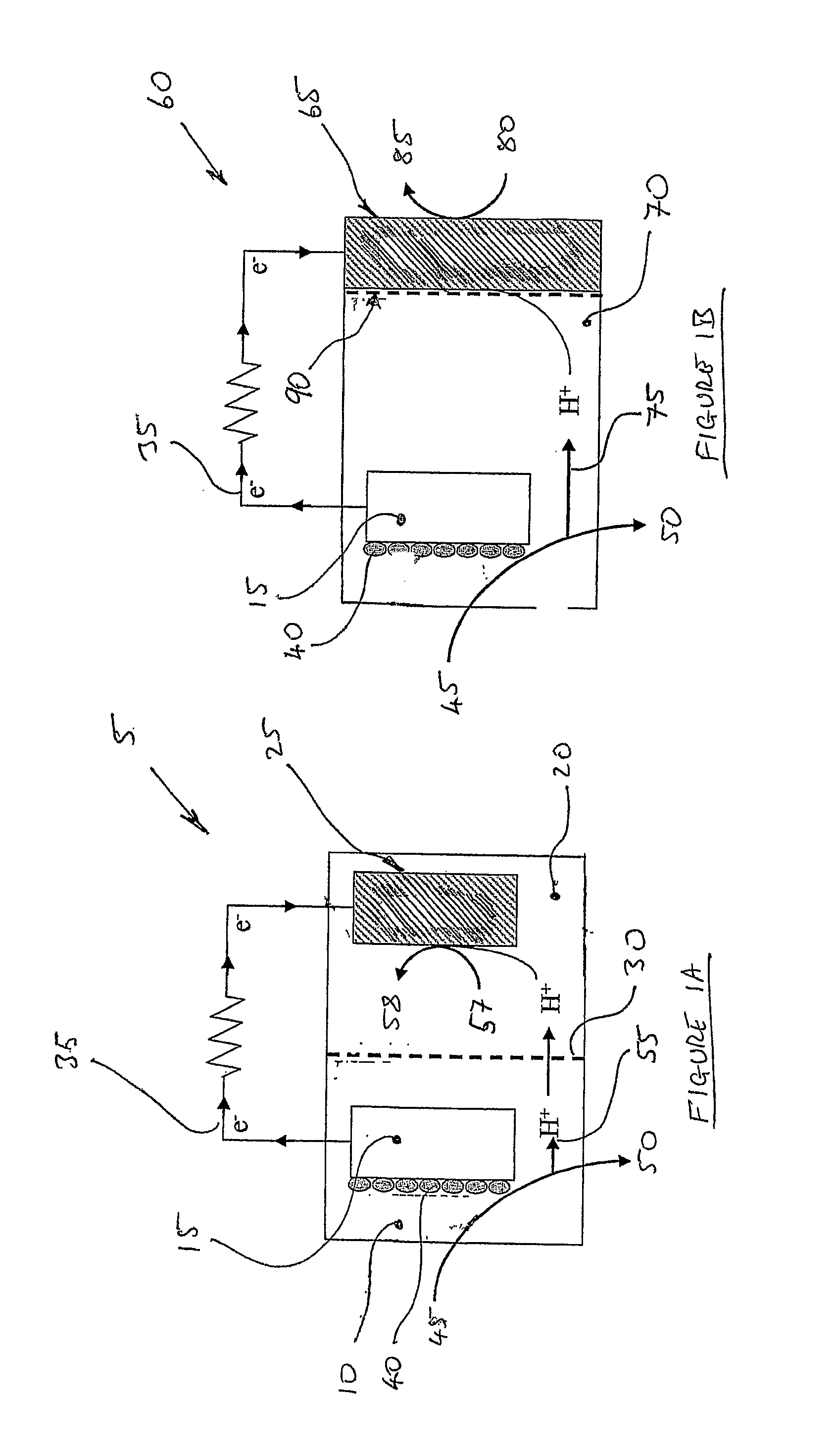
FIGS. 1A and 1B show different microbial fuel cells (MFC) according to the prior art.

With respect to FIG. 1A, shown is a two chamber MFC 5 having an anode chamber 10 and cathode chamber 20. The anode chamber 10 is characterized by being anaerobic so as to prevent released electrons being consumed by oxygen feeding into the chamber 20. Within the chamber is a supply of biomass, such as wastewater, within the chamber 10. The organic material within the wastewater then forms a biofilm 40 on the anode 15 which on degradation of the influent / fuel 45 produces electrons. The anode 15 is connected to an external circuit 35 through which the consequential current flows to the cathode 25 within the cathode chamber 20. Thus, the fuel 45 supplied to the anode chamber 10 is oxidized 50 producing a flow of protons 55 through a proton exchange membrane (PEM) 30 whereby the protons combine with oxygen 57 within the cathode chamber 20 to form water 58.

FIG. 1B shows an alternative arrangement of an M...


PUM


Abstract

A cathode for a fuel cell comprising a catalyst layer; a backing layer mounted to an aperture in a fuel chamber of said fuel cell; 1) wherein said catalyst layer is mounted to the backing layer on a face opposed to the aperture, so as to be in fluid communication with atmospheric oxygen in the case of microbial fuel cell; and 2) wherein said catalyst layer is mounted to the backing layer on a face opposed to the aperture, so as to be in fluid communication with water in the case of microbial electrolysis cell.

Description

FIELD OF THE INVENTIONThe present invention relates to the manufacture and use of a fuel cell and having particular application to microbial fuel cells and microbial electrolysis cells. Specifically the invention relates to an arrangement and construction of a cathode for such a fuel cell.BACKGROUND OF THE INVENTIONMicrobial fuel cells (MFCs) have recently been considered as an alternative and promising way for the direct conversion of the biochemical energy bound to wastewater into electricity without any intermediate step.A MFC is fundamentally an anaerobic process where bacteria grow in the absence of oxygen in a chamber containing an anode and form a biofilm that covers the anode. To generate electricity, bacteria in the anode chamber degrade organic matter (the influent / fuel) and transfer the electrons to the anode. These electrons pass through an external circuit producing current. The digestion of organic matters occurs in anaerobic environment so that the electrons are not c...

Claims


Application Information

Patent Timeline
IPC IPC(8): H01M8/16
CPCH01M4/8605Y02E60/527H01M8/16H01M4/92Y02E60/50C02F3/00H01M4/86H01M8/02H01M8/04
Inventor NG, HOW YONGLEFEBVRE, OLIVIER PATRICKOOI, WAI KEONG
Owner NAT UNIV OF SINGAPORE
Why Eureka
Try Eureka