
Cleaning robot system and method of controlling same

a robot and cleaning technology, applied in the field of robot systems, can solve the problems of reducing the work efficiency of the cleaning robot, no countermeasure against the problem has been established, and the method involves a lot of work, so as to improve the work efficiency of the cleaning work and improve the economy

Inactive Publication Date: 2011-06-09
MITSUI ENG & SHIPBUILD CO LTD
View PDF2 Cites 54 Cited by
  • Summary
  • Abstract
  • Description
  • Claims
  • Application Information

AI Technical Summary

Benefits of technology

[0034]According to the cleaning robot system and the method of controlling the same of the present invention, the cleaning robot system and the method of controlling the same are configured so that plate-shaped members, such as solar cell panels and reflecting mirrors (heliostats) used in photovoltaic power generation and solar thermal power generation systems, are cleaned by at least two types of robots, that is, the cleaning robot having the functions to clean the plate-shaped members and to travel on the surfaces of the plate-shaped members, and the arranging robot having the function to move the cleaning robot from a first plate-shaped member to a different second plate-shaped member. This makes it possible to improve the work efficiency of the cleaning work and also improve the economy.

Problems solved by technology

A problem has been pointed out that heliostats, which are reflecting mirrors used in the system, or panels of a photovoltaic power generation system get dirty with dust, bird droppings, or the like, so that the power generation efficiency is decreased.
However, no countermeasure against the problem has been established yet.
However, this method involves a hard work, and sometimes requires the setting of a scaffold because the work may have to be performed in a high place.
For these reasons, this method leads to a decrease in work efficiency and an increase in costs.
In addition, the poor workability of this method possibly causes a risk of damaging a glass surface of a reflecting mirror, a panel, and the like.
If the power generation systems will be increased in scale further in the future, the problem will tend to become large functionally and economically.
For this reason, panels and reflecting mirrors are likely to get dirty with sand dust, and also, the manual work may be difficult because of a high temperature in some case.
In short, these manual cleaning works have the problem of the safety of a worker and the problem of the risk of damaging a glass surface of a panel or a mirror, which is a target of the work.
In addition, there is also a problem in which an increase in the scale of a power generation system leads to an increase in cleaning costs in proportion, so that the scale effect cannot be achieved.
Consequently, as a power generation system is increased in scale, the proportion of maintenance costs required for the cleaning work for the system is relatively increased.
However, when the frequency and absolute amount of the cleaning work are increased along with an increase in the scale of the power generation system, the initial costs for installing a robot are increased because of an increase in the size of the robot and the like.
Moreover, the operating costs are increased because of energy consumption of the robot and the remote operation manually conducted, in turn leading to deterioration of the economy.
For these reasons, it seems highly likely at the current circumstances that the application of the above-described cleaning system is difficult.
The price (initial costs) of the robot also becomes high.
However, the motive power (operating costs) for moving the robot itself while supporting the weight of the robot is increased to an extent that cannot be ignored.
This is inefficient and deteriorates the economy.
Further, the remote operation requires manpower, so only the work environment for the worker is improved but the economy is not improved.
This is also a cause of an increase in the price of the robots.

Method used


Image

  • Cleaning robot system and method of controlling same
  • Cleaning robot system and method of controlling same
  • Cleaning robot system and method of controlling same

Examples


Embodiment Construction

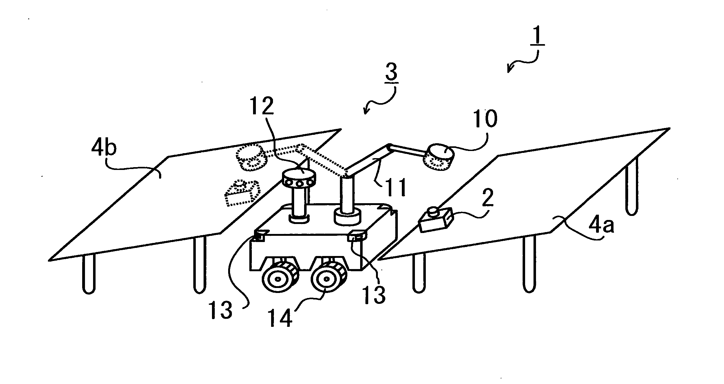
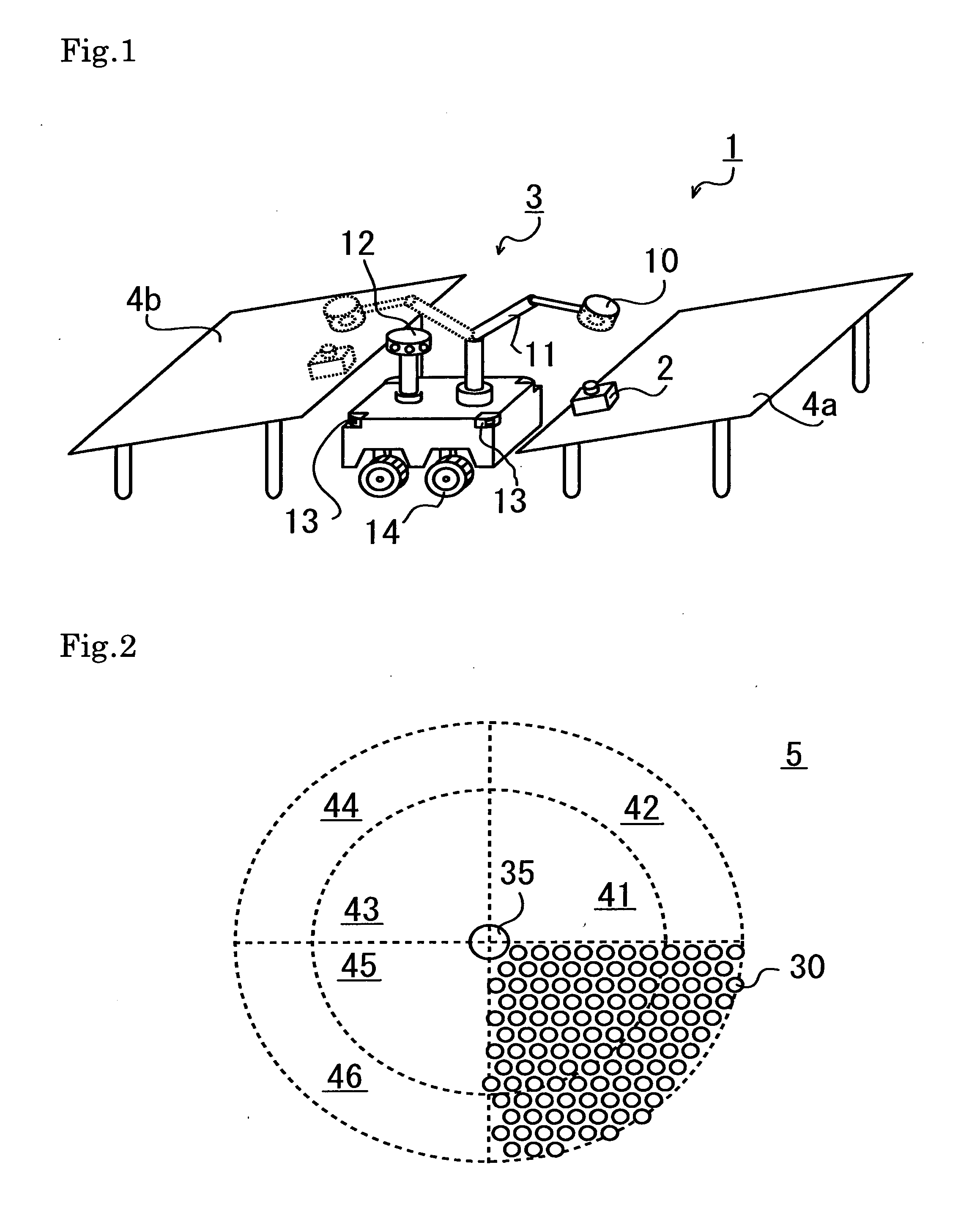
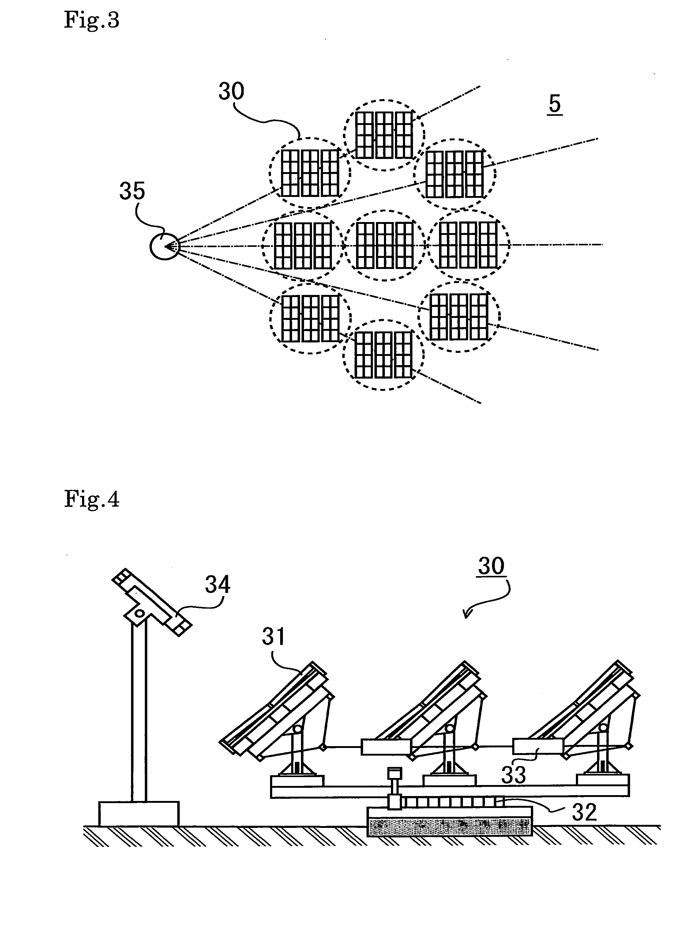
[0041]Hereinafter, a cleaning robot system of an embodiment according to the present invention and a method of controlling the same will be described with reference to the drawings. FIG. 1 shows a configuration of the cleaning robot system of the embodiment according to the present invention.

[0042]The cleaning robot system 1 includes: a cleaning robot 2 for cleaning plate-shaped members 4a, 4b, such as panels for photovoltaic power generation or reflecting mirrors for solar thermal power generation, for example, which are to be cleaned; an arranging robot 3 for moving the cleaning robot 2 from the first plate-shaped member 4a to the second plate-shaped member 4b. The cleaning robot 2 has, for example, a device configured to spray water, a cleaning liquid, and the like for cleaning, and a cleaning function to clean a surface of each of the plate-shaped members 4 with a rotary brush or the like, and also has a traveling function to travel on the surface of each of the plate-shaped mem...


PUM


Abstract

Provided is a cleaning robot system and a method of controlling the same for economically cleaning, with high workability, plate-shaped members, such as solar cell panels and reflecting mirrors used in photovoltaic power generation and solar thermal power generation systems. A cleaning robot system (1) for cleaning planar or curved plate-shaped members (4a), (4b) that are panels for photovoltaic power generation or reflecting mirrors for solar thermal power generation includes: a large number of cleaning robots (2) each having a function to travel on each of the plate-shaped members (4) which are to be cleaned and a function to clean the plate-shaped members (4); and an arranging robot (3) having a conveying function to move any of the cleaning robots (2) from a first one (4a) of the plate-shaped members to a second one (4b) of the plate-shaped members. Each of the cleaning robots (2) has a suction mechanism for performing cleaning while attaching onto one of the plate-shaped members (4), and the large number of cleaning robots (2) and a smaller number of the arranging robots (3) than that of the cleaning robots (2) cooperate together to clean the plate-shaped members (4) placed in a photovoltaic power generation or solar thermal power generation plant.

Description

TECHNICAL FIELD[0001]The present invention relates to a robot system for cleaning a glass surface and the like, among service robots or field robots. Particularly, the present invention relates to a cleaning robot system for cleaning power generating elements called as solar panels for photovoltaic power generation, reflecting mirrors used for solar thermal power generation, and the like.BACKGROUND ART[0002]In recent years, large-scale photovoltaic (solar cells and the like) or solar thermal (photovoltaic collecting systems and the like) power generation systems with power outputs of as much as several hundred thousand kilowatts have been widespread. For example, as the solar thermal power generation systems, which generate electric power by collecting the photovoltaic, a beam-down type solar thermal power generation system has been known (refer to Patent Document 1). In the beam-down type solar thermal power generation system, the photovoltaic is reflected toward an upper side of a...

Claims


Application Information

Patent Timeline
Patent Type & Authority Applications(United States)
IPC IPC(8): B25J13/00
CPCB08B1/00B08B3/024B25J5/00F24J2/461Y02E10/52F24J2002/1076F24J2002/1085H01L31/042Y02E10/40F24J2/542H02S40/10F24S2023/874F24S30/452F24S2023/87F24S40/20Y02E10/50B08B1/12
Inventor HISATANI, MASUJIROOOHASHI, HIROTAKAOKU, KOUNOSUKETSUKADA, JUNTAKEHARA, TORU
Owner MITSUI ENG & SHIPBUILD CO LTD
Features
  • Generate Ideas
  • Intellectual Property
  • Life Sciences
  • Materials
  • Tech Scout
  • Unparalleled Data Quality
  • Higher Quality Content
  • 60% Fewer Hallucinations
Learn More