
Method and Apparatus for Borehole Positioning

a technology for positioning and wellbore, applied in the direction of survey, borehole/well accessories, construction, etc., can solve the problems of limiting the accuracy of this measurement and the introduction of additional noise in the measured signal by the casing

Inactive Publication Date: 2011-06-16
BAKER HUGHES INC
View PDF24 Cites 44 Cited by
  • Summary
  • Abstract
  • Description
  • Claims
  • Application Information

AI Technical Summary

Benefits of technology

The patent describes methods and apparatus for drilling boreholes. One method involves transmitting signals into the earth formation and receiving signals from at least three sensors that are spaced apart. The signals can be transmitted using acoustic, electromagnetic, or magnetic signals. The received signals are used to estimate the path of the borehole. Another method involves using multiple transmitters and a single sensor to estimate the path of the borehole. The patent also describes certain features of drilling multiple boreholes. Overall, the patent provides technical means for accurately drilling boreholes in the earth formation.

Problems solved by technology

The measured signal due directly to the earth's magnetic field is a problem, limiting the accuracy of this measurement.
Residual magnetism of the casing introduces additional noise in the measured signal.

Method used


Image

  • Method and Apparatus for Borehole Positioning
  • Method and Apparatus for Borehole Positioning
  • Method and Apparatus for Borehole Positioning

Examples


Embodiment Construction

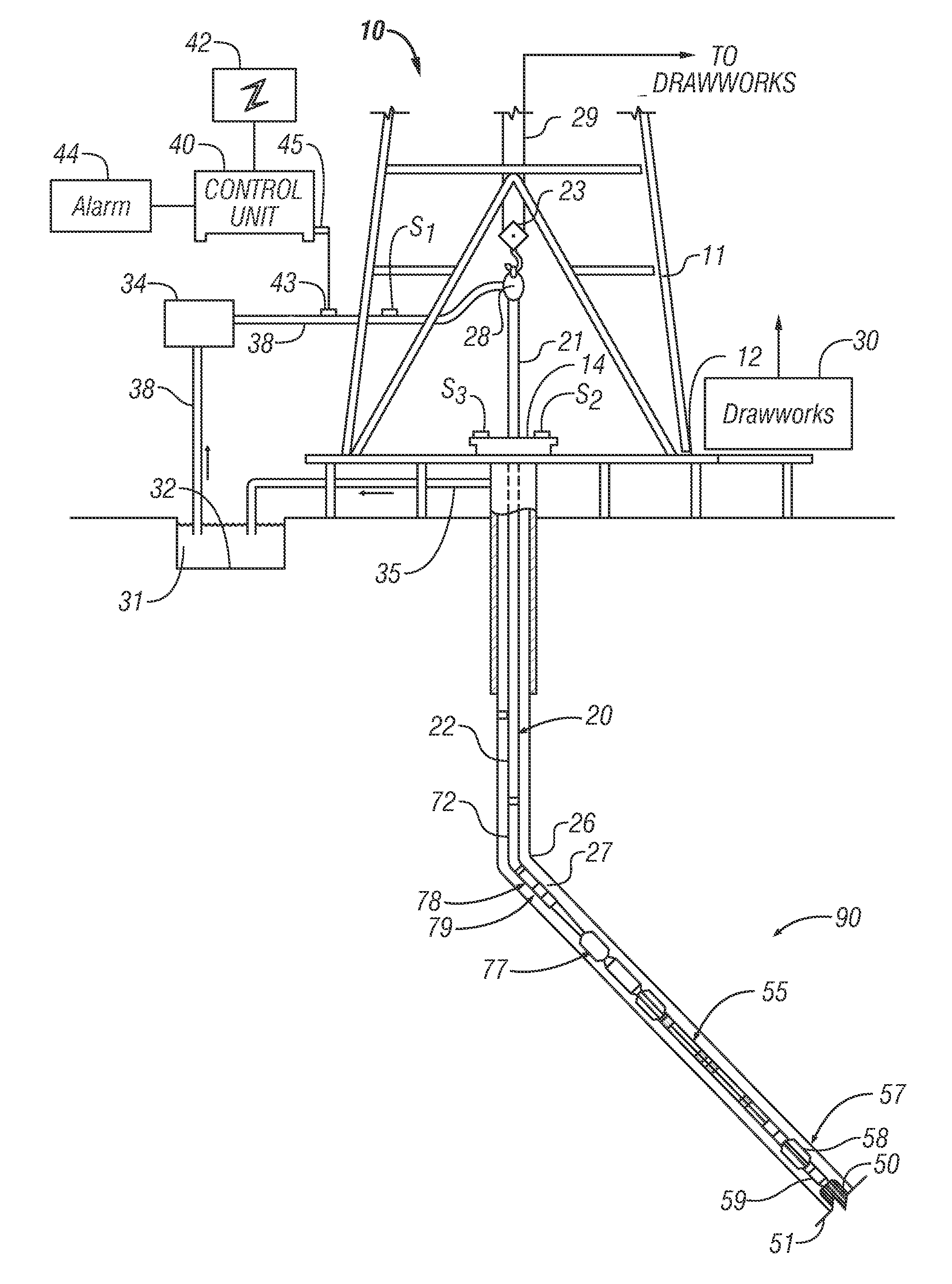
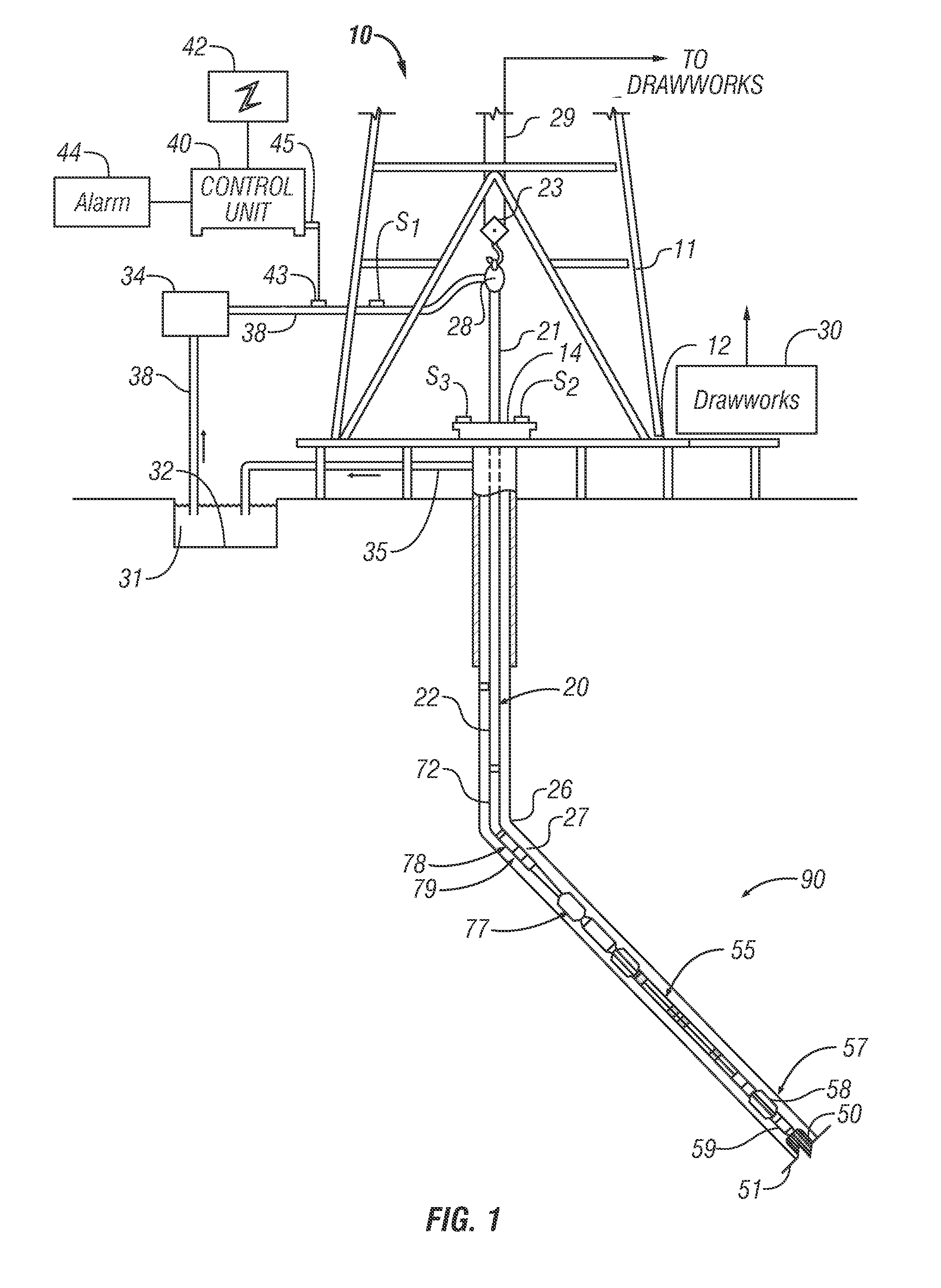
[0022]FIG. 1 shows a schematic diagram of a drilling system 10 with a drill string 20 carrying a drilling assembly 90 (also referred to as the bottomhole assembly, or “BHA”) conveyed in a “borehole” or “borehole”26 for drilling the borehole. The drilling system 10 includes a conventional derrick 11 erected on a floor 12 which supports a rotary table 14 that is rotated by a prime mover such as an electric motor (not shown) at a desired rotational speed. The drill string 20 includes a tubing such as a drill pipe 22 or a coiled-tubing extending downward from the surface into the borehole 26. The drill string 20 is pushed into the borehole 26 when a drill pipe 22 is used as the tubing. For coiled-tubing applications, a tubing injector, such as an injector (not shown), however, is used to move the tubing from a source thereof, such as a reel (not shown), to the borehole 26. The drill bit 50 attached to the end of the drill string breaks up the geological formations when it is rotated to ...


PUM


Abstract

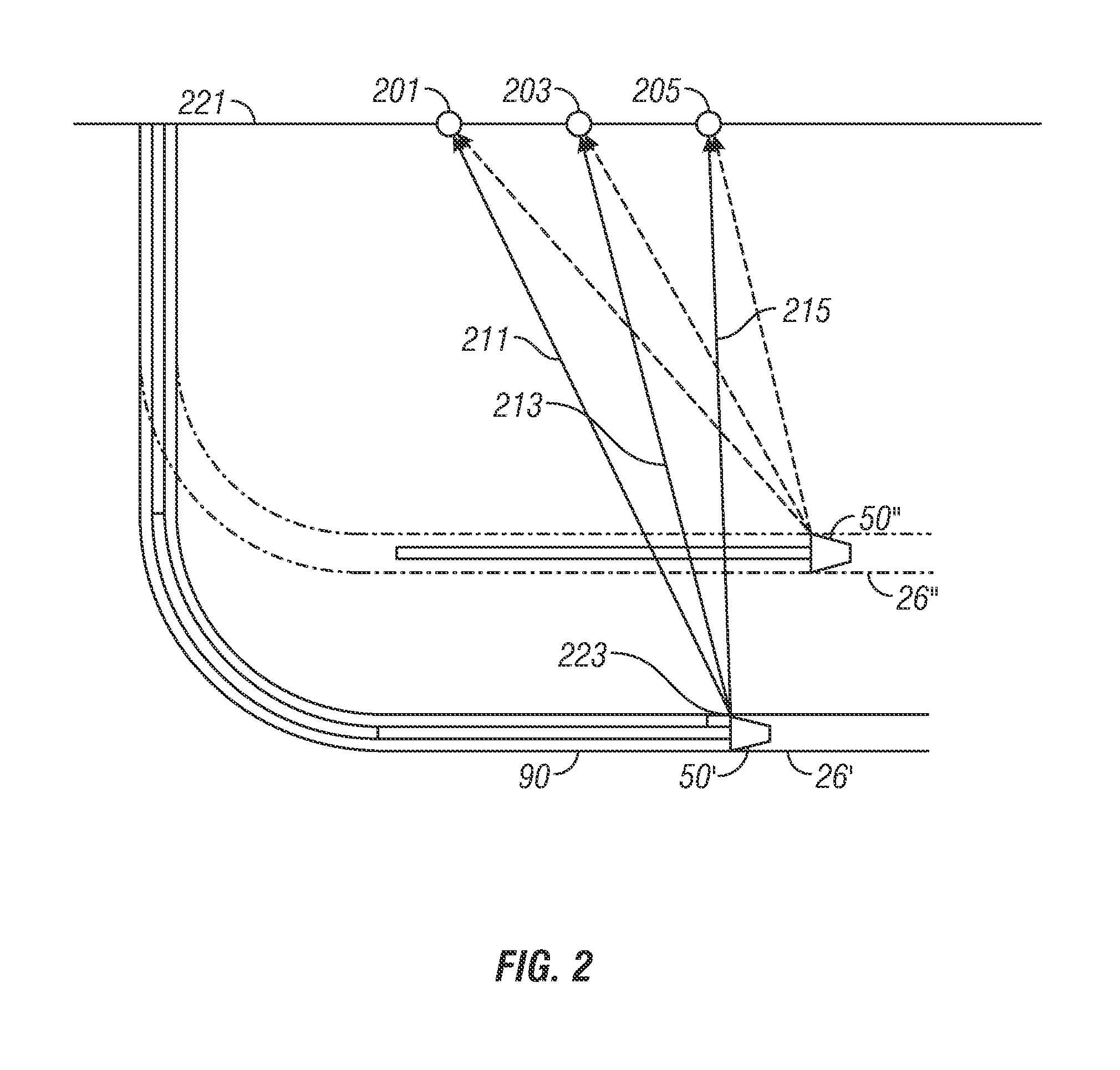
A method of drilling boreholes is provided. The method, according to one embodiment, may include drilling a borehole, transmitting a signal into the earth formation, receiving signals at least three spaced sensors responsive to the transmitted signals and estimating a path of the borehole using the signals received by the at least three sensors. In another aspect, the method may include drilling a borehole, transmitting signals into the earth formation from at least three spaced transmitters, receiving signals at least one sensor responsive to the transmitted signals and estimating a path of the borehole using the signals received by the at least one sensor.

Description

CROSS-REFERENCE TO RELATED APPLICATIONS[0001]This application takes priority from U.S. Provisional Patent Application Ser. No. 61 / 285,349, filed on Dec. 10, 2009.BACKGROUND OF THE DISCLOSURE[0002]1. Field of the Disclosure[0003]This disclosure relates generally to apparatus and methods for drilling wellbores for production of hydrocarbons.[0004]2. Background of the Art[0005]Wellbores (or boreholes) are drilled in earth formations to develop reservoirs for the production of hydrocarbons (oil and gas). It is often desirable to drill multiple wellbores in a formation in predetermined relationships to an existing well. For example, it is sometimes desirable to drill a number of closely spaced horizontal wellbores for recovery of hydrocarbons from a reservoir. A variety of methods, including seismic, magnetic and electromagnetic methods, have been used for drilling such multiple wellbores.[0006]The magnetic methods generally fall into two categories. In the first category, referred to as...

Claims


Application Information

Patent Timeline
Patent Type & Authority Applications(United States)
IPC IPC(8): E21B47/02
CPCE21B43/305G01V1/42E21B47/02224E21B47/02208E21B47/0224E21B47/0232
Inventor KRUEGER, VOLKERWITTE, JOHANNES
Owner BAKER HUGHES INC
Learn More