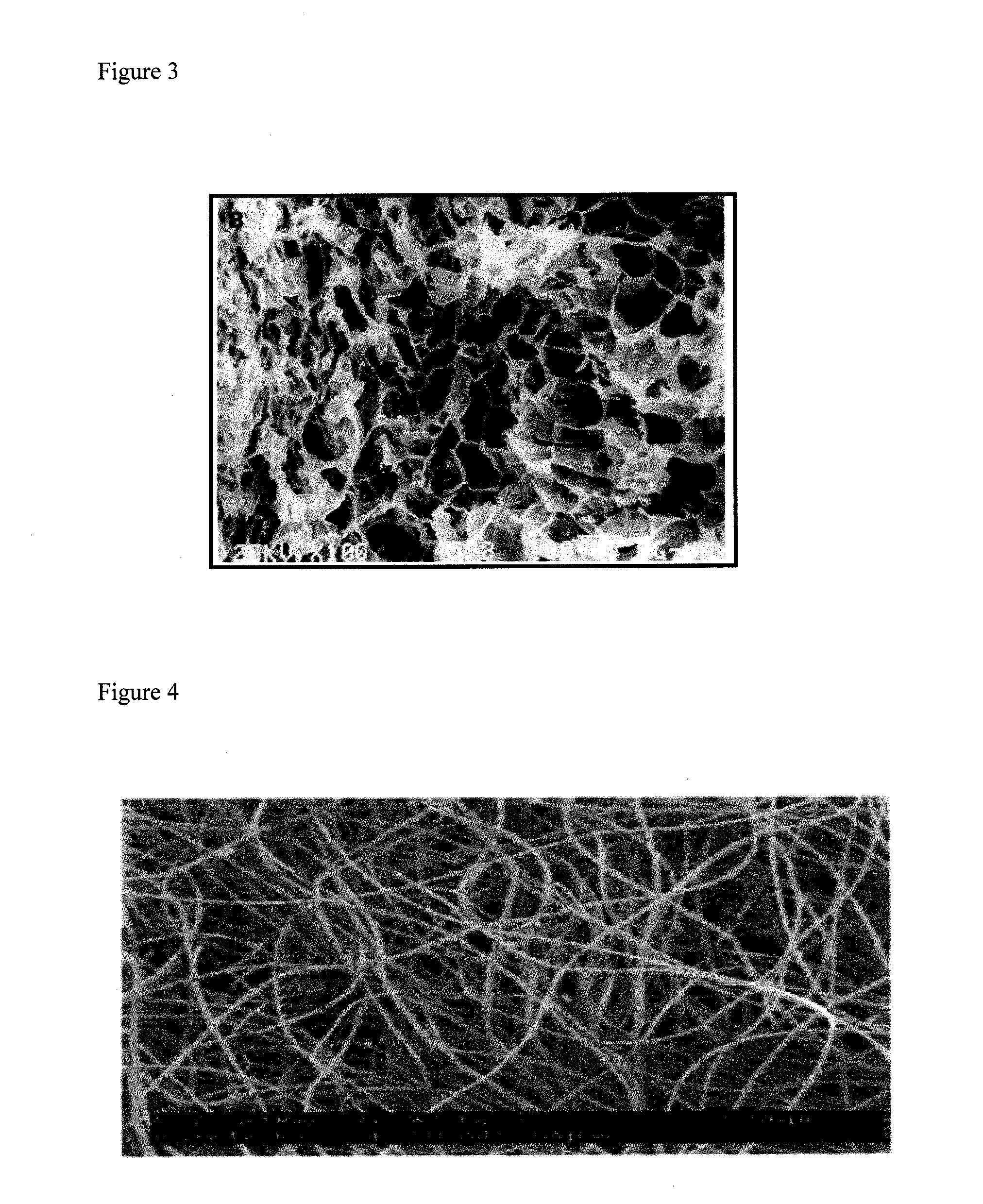
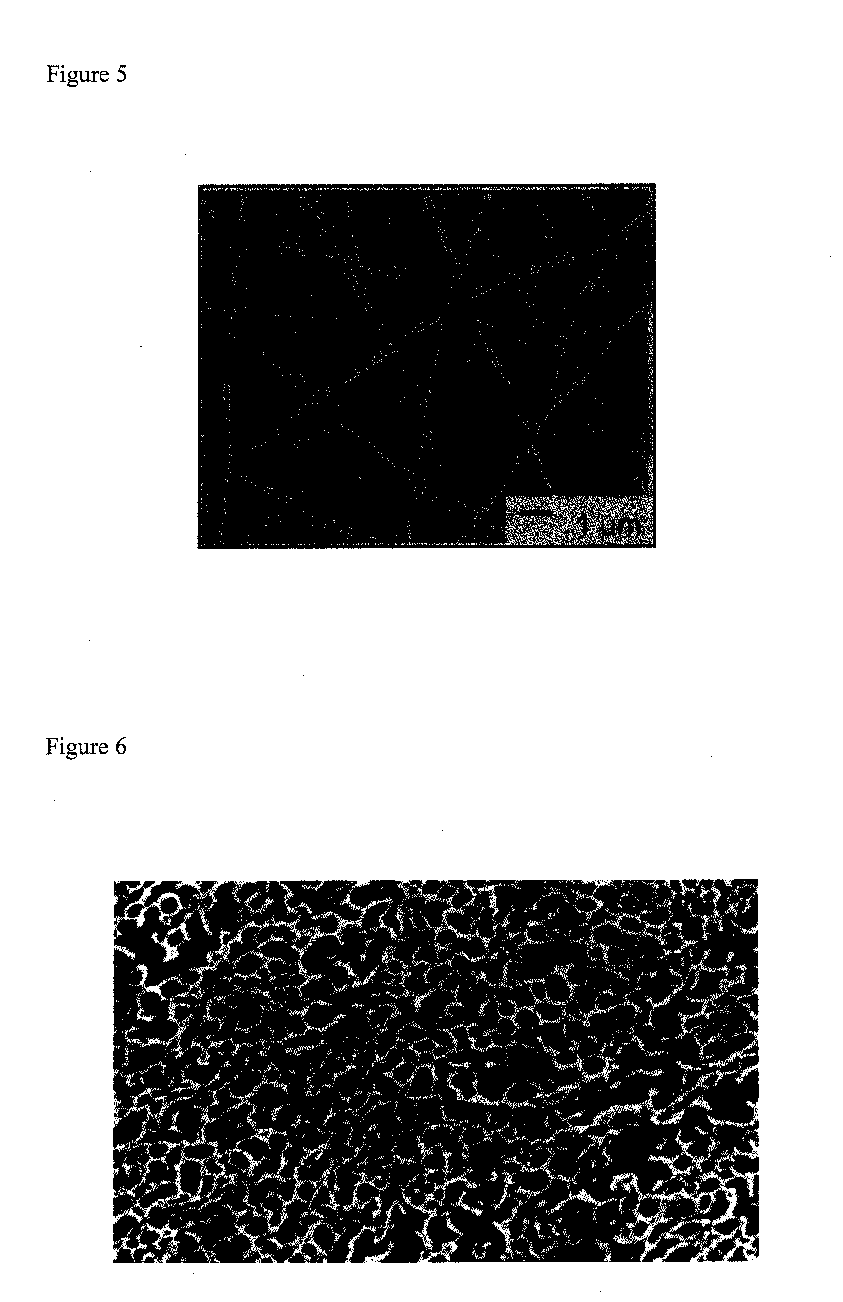
Nanofiber scaffold

a technology of nanofiber and scaffold, which is applied in the field of nanofiber scaffold, can solve the problems of reducing the ability of the heart to pump blood effectively, affecting the formation of gap junctions, and permanent death of a section of heart muscle, and achieves the effects of reducing the formation of gap junctions, and facilitating removal

a technology of nanofiber and scaffold, which is applied in the field of nanofiber scaffold, can solve the problems of reducing the ability of the heart to pump blood effectively, affecting the formation of gap junctions, and permanent death of a section of heart muscle, and achieves the effects of reducing the formation of gap junctions, and facilitating removal

US20110142804A1Active Publication Date: 2011-06-16BIOSURFACES +1

Image

  • Nanofiber scaffold
  • Nanofiber scaffold
  • Nanofiber scaffold

Examples


Embodiment Construction

[0047]The device of the teachings herein, referred to as the “BioGenerator”, is a device to encapsulate hMSCs while allowing factors they secrete to diffuse through the capsule. There are several distinct advantages for utilizing this device over previous delivery methods in that this system: provides targeted delivery of hMSCs eliminating any need for cell homing; delivers factors directly to the infarct site eliminating any need for large numbers of human MSCs due to potential off-target delivery; localizes human MSCs directly to one area eliminating or minimizing off-target effects; is minimally invasive; deliverable by catheter; and is removable.

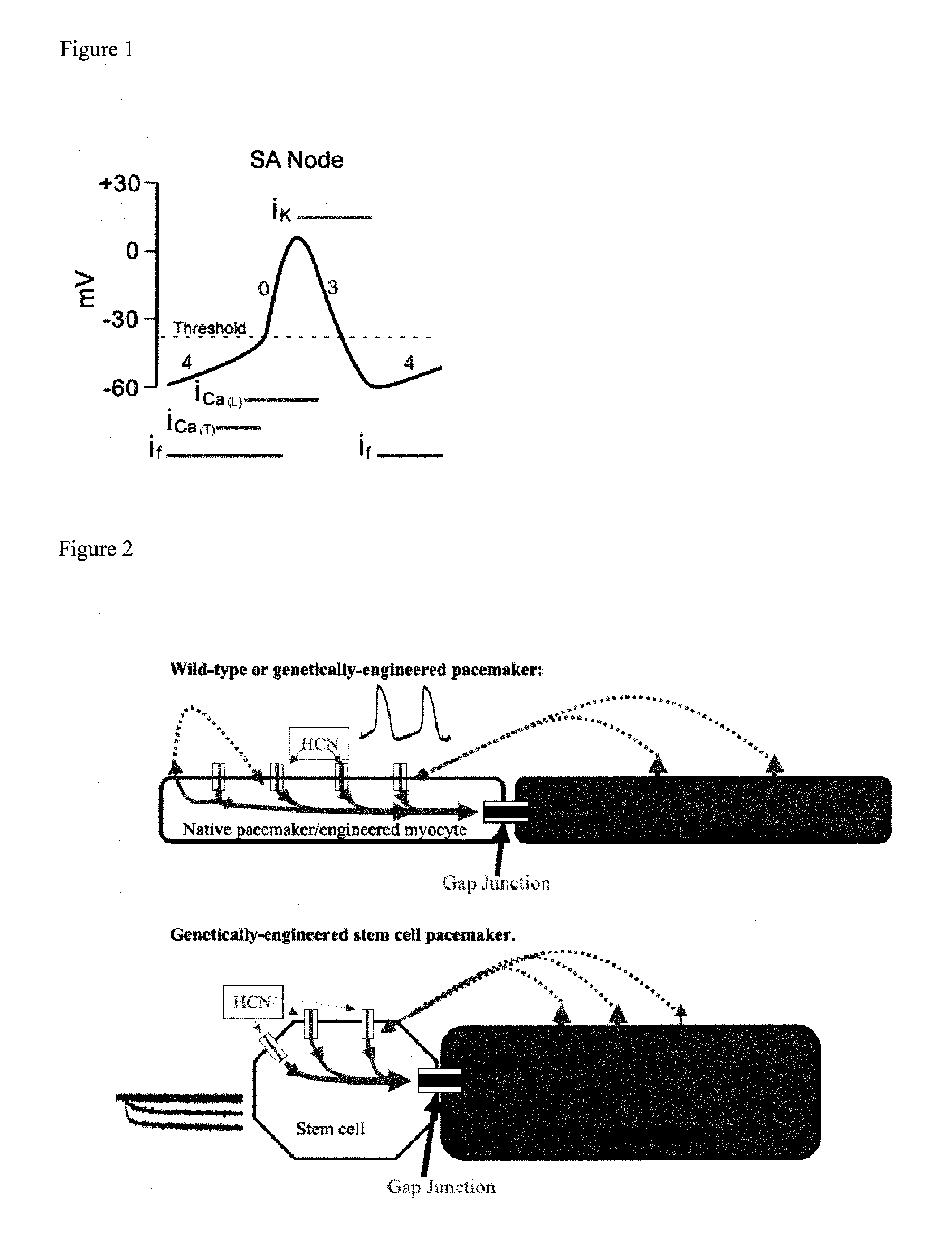
[0048]One embodiment of the invention is a Human Mesenchymal Stem Cell (hMSC) driven Biological Pacemaker. In a normal pacemaker cell, the cell's own depolarization initiates an action potential in the cell. This action potential is then transmitted to other cells via gap junctions, passing down the current. For adult mesenchymal stem ce...


PUM

PropertyMeasurementUnit
diameteraaaaaaaaaa
diameteraaaaaaaaaa
thickaaaaaaaaaa

Abstract

The invention is directed to a device and method to prevent migration of Human Mesenchymal Stem Cells (hMSCs) from a delivery site while allowing communication between the stem cells and native cardiomyocytes. The device is characterized by scaffold pore size, fiber diameter and biomaterial selection. The invention includes a two part polyurethane scaffold that prevents migration of stem cells, allows gap junction formation through pores and is packaged for minimally invasive delivery.

Description

RELATED APPLICATIONS[0001]This application claims priority to and the benefit of U.S. Provisional application 61 / 264,440, filed Nov. 25, 2009, the contents of which are incorporated herein in their entirety.BACKGROUND OF THE INVENTION[0002]Heart disease is the number one cause of death in the United States accounting for one in every four deaths. Coronary heart disease is the most common type, causing the deaths of over 400,000 people in 2005. In coronary heart disease, one or more coronary arteries become occluded. The subsequent lack of oxygen and nutrients often result in permanent death of a section of heart muscle. This reduces the ability of the heart to pump blood effectively. Despite the body's compensatory measures, in many patients there is a steady decline in cardiac function until failure occurs due to a lack of native myocardial regenerative ability. Several investigators have evaluated using adult human mesenchymal stem cells (hMSCs) to repair the damaged heart muscle,...

Claims


Application Information

Patent Timeline
16 Jun 2011
Publication
US20110142804A1
IPC
A61K35/12; C12N11/00; C12N11/02; C12N11/08; A61P9/00
CPC
A61L27/18; A61L27/3834; A61L27/56; A61L2400/12; C12N5/0068; C12N2533/30; C12N11/08; C08L75/04
Inventors
GAUDETTE, GLENN; PHANEUF, MATTHEW D.