
Methods for regenerating acidic ion-exchange resins and reusing regenerants in such methods

a technology of acidic ion exchange resin and regenerant, which is applied in the field of biofuels, can solve the problems of limiting the utilization of biomass-derived pyrolysis oil as a biofuel, limiting the commercial application of conventional biomass-derived pyrolysis oil, and limiting the use of metals in biomass-derived pyrolysis oil, so as to improve the phase stability

Active Publication Date: 2011-06-23
UOP LLC
View PDF26 Cites 54 Cited by
  • Summary
  • Abstract
  • Description
  • Claims
  • Application Information

AI Technical Summary

Benefits of technology

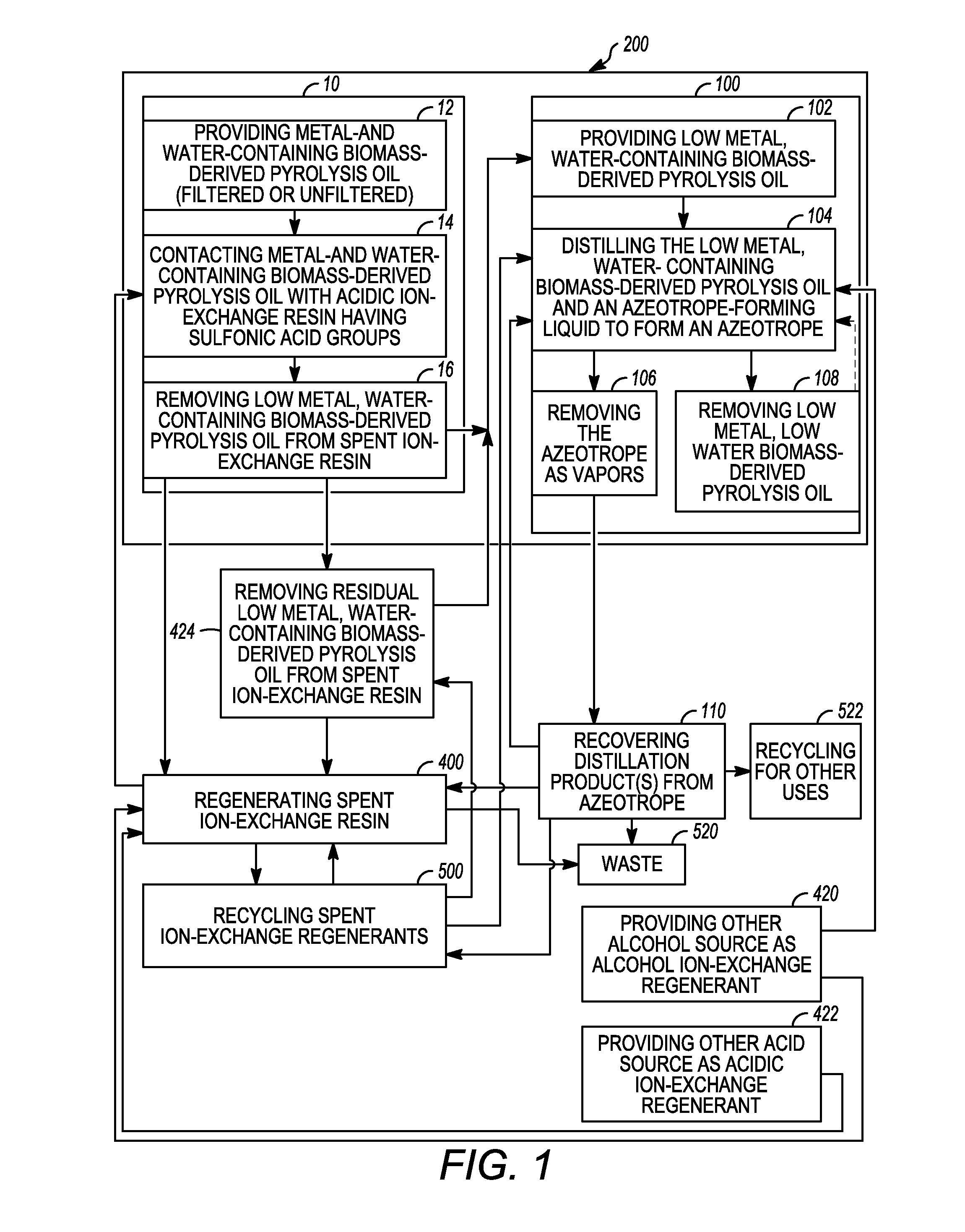
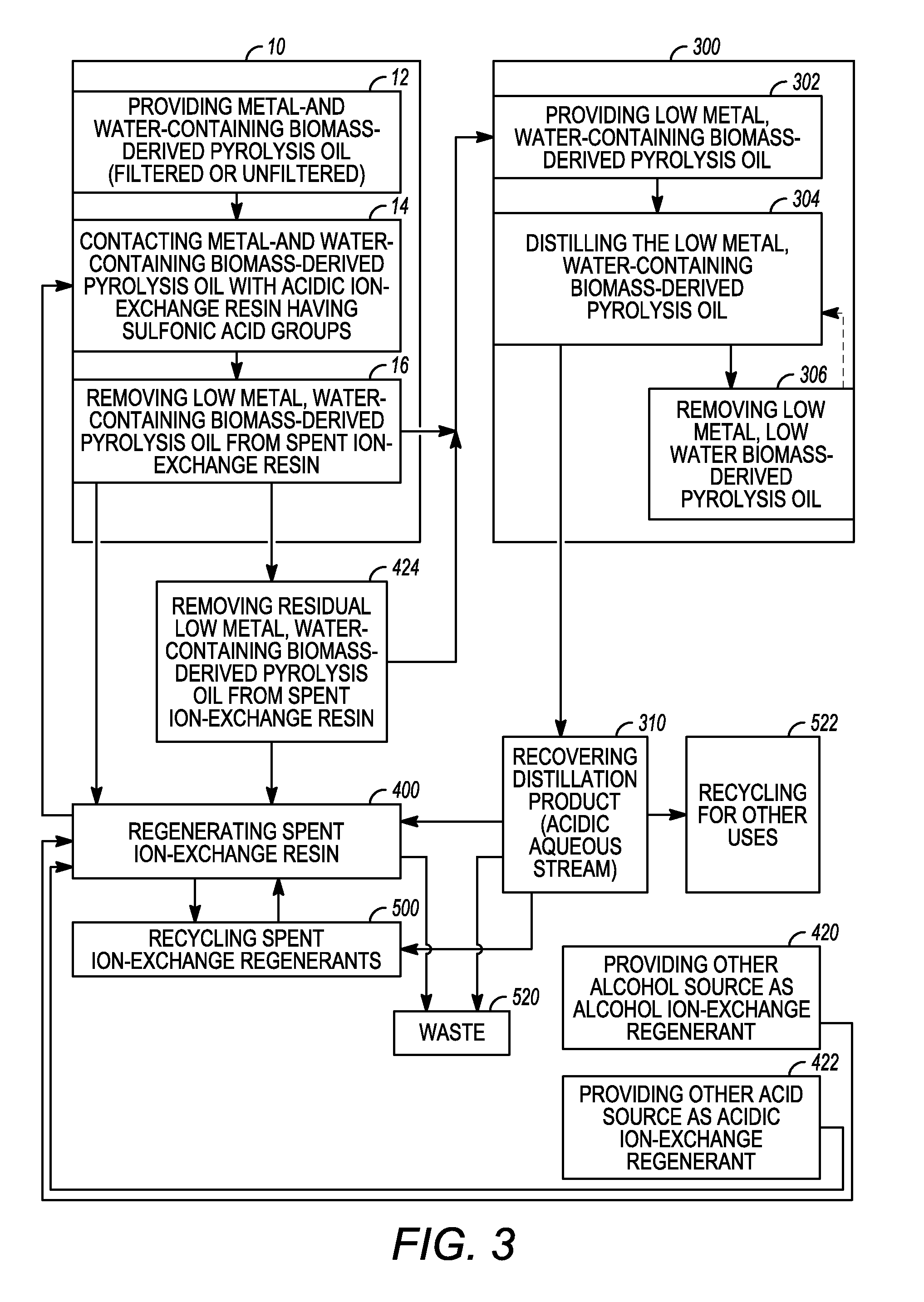
[0010]Methods are provided for the regeneration of a spent acidic ion-exchange resin and recycling thereof. In accordance with an exemplary embodiment of the present invention, the method comprises contacting a spent ion-exchange resin with an alcohol ion-exchange regenerant. The spent ion-exchange resin is thereafter contacted with an acidic ion-exchange regenerant to recharge the spent ion-exchange resin to produce a regenerated acidic ion-exchange resin. Metal- and water-containing biomass-derived pyrolysis oil is then contacted with the regenerated acidic ion-exchange resin to produce low metal, low water biomass-derived pyrolysis oil which contains residual alcohol ion-exchange regenerant to improve its phase stability.

Problems solved by technology

However, biomass-derived pyrolysis oil is a complex, highly oxygenated organic liquid having properties that currently limit its utilization as a biofuel.
For example, metals in the conventional biomass-derived pyrolysis oil limit its commercial applications.
Environmental restrictions may limit such total emissions.
In addition, when the biomass-derived pyrolysis oil is used as feedstock in catalytic processes to make transportation fuel, the metals in the oil foul downstream equipment and inhibit or inactivate catalysts.
While ion-exchange resins are used to remove metals from aqueous solutions, they have not been effective in removing metals from biomass-derived pyrolysis oil because of their susceptibility to fouling.
Ion-exchange resin is known to foul irreversibly when exposed to non-polar oils such as those found in the water insoluble tars of biomass-derived pyrolysis oil.
The oil will readily coat each ion-exchange bead and severely inhibit the bead's ability to adsorb ionic materials from the organic stream.
As the oil is also sticky, it will result in agglomeration of the ion-exchange beads, producing channeling of the bed.
The agglomeration can also significantly affect backwashing.
However, such washes are not entirely effective.
In addition, while spent ion-exchange resins, if not too badly fouled, can be regenerated, conventional regeneration requires an extremely labor intensive and costly method.
In addition, the use of conventional acidic ion-exchange regenerants, such as a concentrated hydrochloric or sulfuric acid solution, may be costly and disposal of the spent acidic ion-exchange regenerants may be difficult.
Other properties that limit the commercial application of conventional biomass-derived pyrolysis oil include its high water content.
Biomass-derived pyrolysis oil may often be stored in tanks or the like for long periods of time resulting in increases in viscosity, phase separation and / or solids formation during such storage.
The high water content of biomass-derived pyrolysis oil increases the storage instability of the oil.
Biomass-derived pyrolysis oil cannot be conventionally distilled to completely remove water, as phase separation and / or solids formation result as volatiles are removed.
Conventional biomass-derived pyrolysis oil may also be contaminated with char fragments and other insolubles produced during biomass pyrolysis.
Char contributes to thermal instability of the oil.
Separation of the char fragments from the biomass-derived pyrolysis oil has proven very difficult.
For example, conventional liquid filtration is difficult as the liquid biomass-derived pyrolysis oil can have a gel-like consistency.

Method used


Image

  • Methods for regenerating acidic ion-exchange resins and reusing regenerants in such methods
  • Methods for regenerating acidic ion-exchange resins and reusing regenerants in such methods
  • Methods for regenerating acidic ion-exchange resins and reusing regenerants in such methods

Examples


Embodiment Construction

[0016]The following detailed description of the invention is merely exemplary in nature and is not intended to limit the invention or the application and uses of the invention. Furthermore, there is no intention to be bound by any theory presented in the preceding background of the invention or the following detailed description of the invention.

[0017]Various exemplary embodiments of the present invention are directed to low metal, low water biomass-derived pyrolysis oils and methods for producing the same and methods for regenerating acidic ion-exchange resins and reusing ion-exchange regenerants for use in the methods for producing low metal, low water biomass-derived pyrolysis oil. It should be appreciated that while the oil produced according to exemplary embodiments of the present invention is generally described herein as a “low metal, low water biomass-derived pyrolysis oil”, this term generally includes any oil produced having a lower total metal concentration and weight per...


PUM

PropertyMeasurementUnit
temperaturesaaaaaaaaaa
pressureaaaaaaaaaa
pressureaaaaaaaaaa

Abstract

Methods for regenerating acidic ion-exchange resins and reusing regenerants in such methods are provided. A spent ion-exchange resin is contacted with an alcohol ion-exchange regenerant. The spent ion-exchange resin is thereafter contacted with an acidic ion-exchange regenerant to recharge the acidic ion-exchange resin to produce a regenerated acidic ion-exchange resin. Metal- and water-containing biomass-derived pyrolysis oil is then contacted with the regenerated acidic ion-exchange resin to produce low metal, water-containing biomass-derived pyrolysis oil. The regenerated acidic ion-exchange resin may be recycled. The spent alcohol and acid ion-exchange regenerants may be recovered and recycled.

Description

CROSS-REFERENCE TO RELATED APPLICATIONS[0001]This application is related to co-pending U.S. application Ser. No. ______ entitled “LOW WATER BIOMASS-DERIVED PYROLYSIS OIL AND PROCESSES FOR PRODUCING THE SAME”, U.S. application Ser. No. ______ entitled “LOW METAL BIOMASS-DERIVED PYROLYSIS OILS AND PROCESSES FOR PRODUCING THE SAME”, and U.S. application Ser. No. ______ entitled “LOW METAL, LOW WATER BIOMASS-DERIVED PYROLYSIS OILS AND METHODS FOR PRODUCING THE SAME”, filed concurrently herewith on ______, and which are incorporated by reference herein in their entirety.FIELD OF THE INVENTION[0002]The present invention generally relates to biofuels and methods for producing biofuels, and more particularly relates to methods for regenerating acidic ion-exchange resins and reusing ion-exchange regenerants in such methods.DESCRIPTION OF RELATED ART[0003]Fast pyrolysis is a process during which organic biomass materials, such as wood waste, agricultural waste, etc. are rapidly heated to abou...

Claims


Application Information

Patent Timeline
Patent Type & Authority Applications(United States)
IPC IPC(8): C10L1/12
CPCB01J49/0069C10L1/02C10G2300/1011B01D15/362G01N30/50G01N30/96B01D15/20B01D15/203B01J49/0008Y02P30/20B01J49/06B01J49/53
Inventor BRANDVOLD, TIMOTHY A.FREY, STANLEY J.ABRAHAMIAN, VASKENTRAYNOR, THOMAS
Owner UOP LLC
Learn More