
Process for Continuous On-Chip Flow Injection Analysis

a flow injection and flow analysis technology, applied in the field of on-chip flow injection analysis devices and processes, can solve the problems of difficult maintenance of balance, difficult to reproduce sample plug formation, and complex microfabrication procedures for various components, and achieve simple and inexpensive devices and processes. , the effect of reliable devices and processes

Inactive Publication Date: 2011-06-23
CRYSTAL VISION MICROSYST
View PDF7 Cites 4 Cited by
  • Summary
  • Abstract
  • Description
  • Claims
  • Application Information

AI Technical Summary

Benefits of technology

The present invention provides a microfluidic device and process for real-time and / or on-line fluid analysis. The device is simple and inexpensive, and the process is reliable. The device comprises an analyte fluid inlet means, a carrier fluid inlet means, and an injection cross where the two fluids meet. The device also includes a detector cell and a means for momentarily modifying the flow conditions to create a sample plug of analyte fluid. The technical effects of the invention are improved accuracy and efficiency in fluid analysis, as well as reduced costs and complexity.

Problems solved by technology

Although this system proved to be technically feasible, the microfabrication procedures for the various components are very elaborate, excluding commercial production for low added-value applications due to the high costs involved.
Moreover, the proposed solution was based on a complex control for creating sequential injection.
This method of injection rarely results in reproducible sample plug formation, since a delicate balance of static and dynamic pressures in the channel network are required to constrain the analyte to remain in the loop channel.
In a microfluidic system, this balance is difficult to maintain when using external fluid handling equipment such as external pumps and valves.
This solution is not adapted for on-line or real time measurement since the sample analysis is only possible after the long and not accurately predictable necessary time for purging the dead volume.
Also, this solution introduces complexity to the operation of the device, where use is made of three independently controlled syringe pumps.
Finally, reproducibility is difficult to achieve due to dead volumes associated with external tubing and valves, trapped air and elastic components in the external fluid path which are accountable for irreproducible behavior.
This leads to difficulties in performing several equivalent analyses, useful for validation purposes, for instance, what leads to a lack of reliability of the measurements.

Method used


Image

  • Process for Continuous On-Chip Flow Injection Analysis
  • Process for Continuous On-Chip Flow Injection Analysis
  • Process for Continuous On-Chip Flow Injection Analysis

Examples


Embodiment Construction

[0025]In order to facilitate the following description of the present invention, specific terms are defined below.

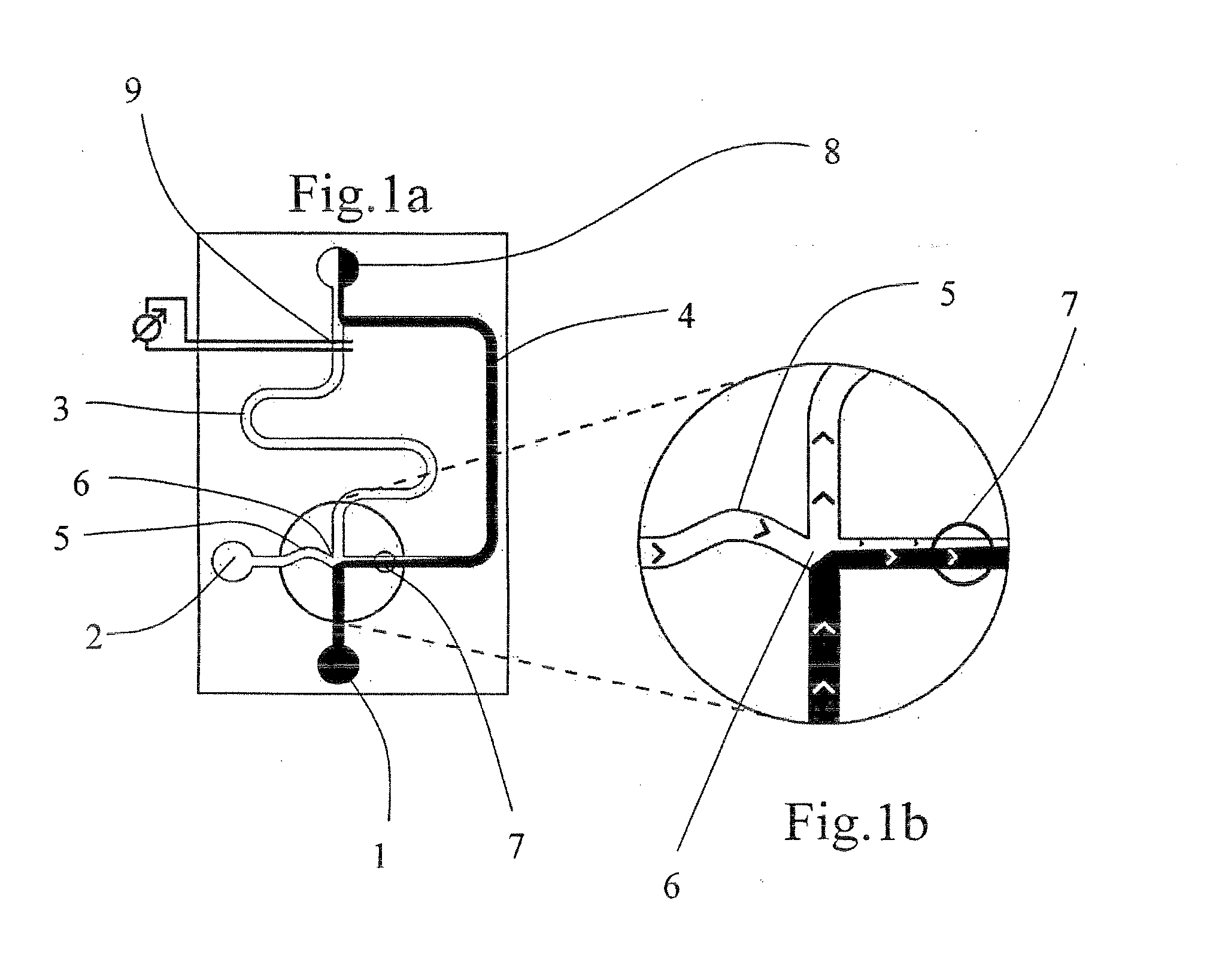
[0026]The terms injection cross, intersection and junction are used interchangeably. These refer to the intersection of the inlet, analytical and bypass channels.

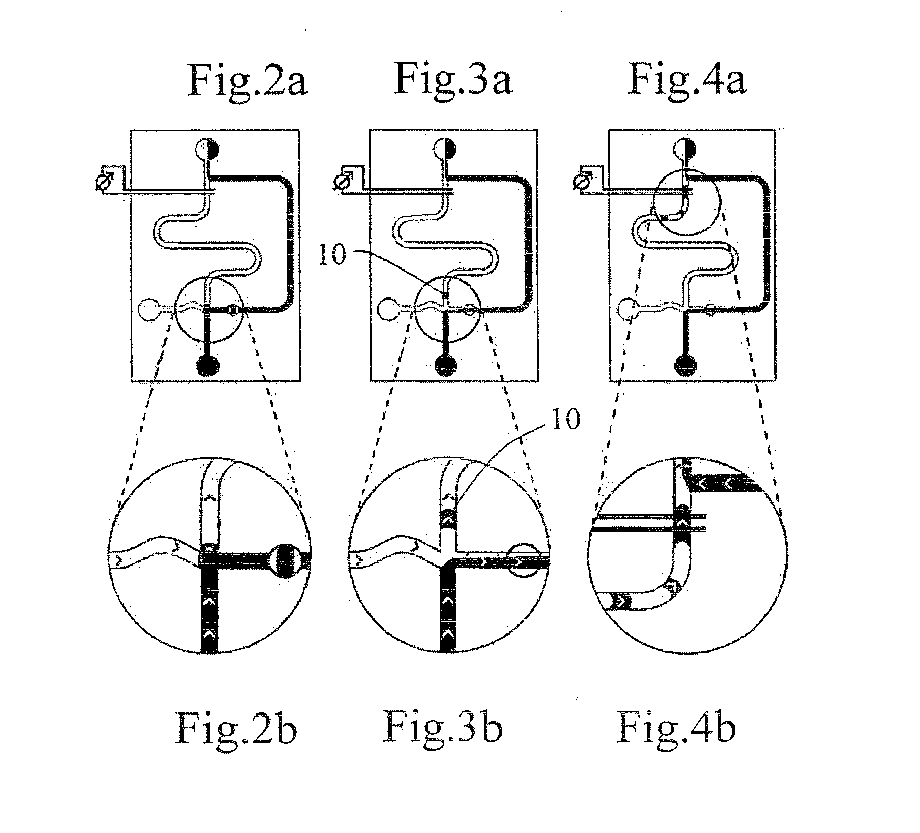
[0027]The terms run mode and standby phase are used interchangeably. These refer to the continuous operation of the device during which time no injection of analyte has occurred, and no injection plug is flowing in the channel network.

[0028]The terms injection mode and analysis phase are used interchangeably. These refer to the continuous operation of the device during which time an injection of analyte has been made, an injection plug is flowing in the channel network and detection cell.

[0029]The terms inlet means, inlet port, and outlet means, outlet port are used interchangeably.

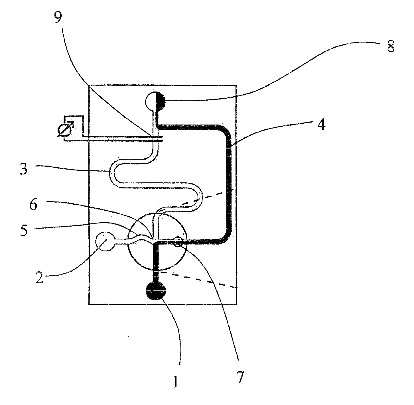
[0030]In the preferred embodiment of the invention, as illustrated by FIGS. 1 to 4, the microfluidic network is composed of inlet me...


PUM

PropertyMeasurementUnit
resistanceaaaaaaaaaa
hydrostatic pressuresaaaaaaaaaa
hydrostatic pressureaaaaaaaaaa

Abstract

A micro-fluidic method for continuous pressure-driven flow injection analysis and a planar microfluidic device intended for pressure driven flow injection analysis are provided. A network of microchannels allows a continuous flow of sample stream on the devices, as well as facile and reproducible analyte plug injection to a reagent or buffer stream on microchip-based devices. The method allows for sequent separation analysis without additional purging cycles.

Description

CROSS REFERENCE TO RELATED APPLICATIONS[0001]This application is a divisional of co-pending U.S. application Ser. No. 11 / 569,927 which is the National Stage of International Application No. PCT / IB2004 / 001909, filed Jun. 4, 2004.BACKGROUND OF THE INVENTION[0002]The present invention concerns a device and a process for on-chip flow analysis. More precisely, it concerns a planar microchip-based device, whereupon a network of microchannels is imparted to allow a flow of sample plug to analyses on the device. The invention is particularly adapted for field-portable chemical laboratories for environmental, military and civil protection uses, high-throughput drug discovery, proteomic analysis or medical diagnostics, and on-line process monitoring.[0003]Demand for highly compact analytical chemical systems incorporating lab-on-chip microfluidic devices is beginning to gain momentum.[0004]To this end, using a fully miniaturized and integrated approach, Tiggelaar et al., “Analysis systems for...

Claims


Application Information

Patent Timeline
Patent Type & Authority Applications(United States)
IPC IPC(8): G01N1/00F15D1/00B01L3/00G01N35/08G01N35/10
CPCB01L3/502746B01L3/502784B01L2200/0605B01L2200/0673G01N2035/1034B01L2300/0816B01L2300/0877B01L2400/0622G01N35/085B01L2300/0645Y10T137/0396
Inventor GILBERT, SCOTT E.SCHLUND, MARIO
Owner CRYSTAL VISION MICROSYST
Learn More