[0013]In view of the foregoing, various embodiments of the present invention provide synthetic jet actuator systems, apparatus, and synthetic jet actuators, which include and employ an arc-forming subsystem either in conjunction with or in combination with a dual bimorph subsystem as a dynamic flow control device. Various embodiments of the present invention also include
software, program product,
firmware, methods, and controllers which provide for
synchronizing and timing electronic firing of electrodes of the arc-forming subsystem to coincide with movement of the walls of a chamber of the dual bimorph subsystem of a synthetic jet actuator to thereby selectively enhance performance and / or to provide an extended operating margin to the dual bimorph subsystem of the synthetic jet actuator. Various embodiments of the present invention further provide a synthetic jet actuator comprising a diaphragm /
bellows-based dual bimorph synthetic jet actuator enhanced with electrodes and interfaced with a
control system to synchronize application of the
electrode actuation components of the synthetic jet actuator with the actuation of the dual bimorph actuation components.
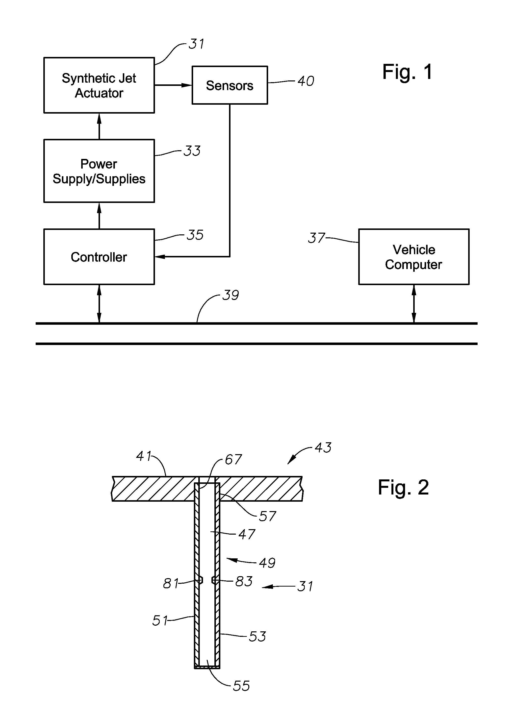
[0014]More specifically, an example of an embodiment of a synthetic jet actuator
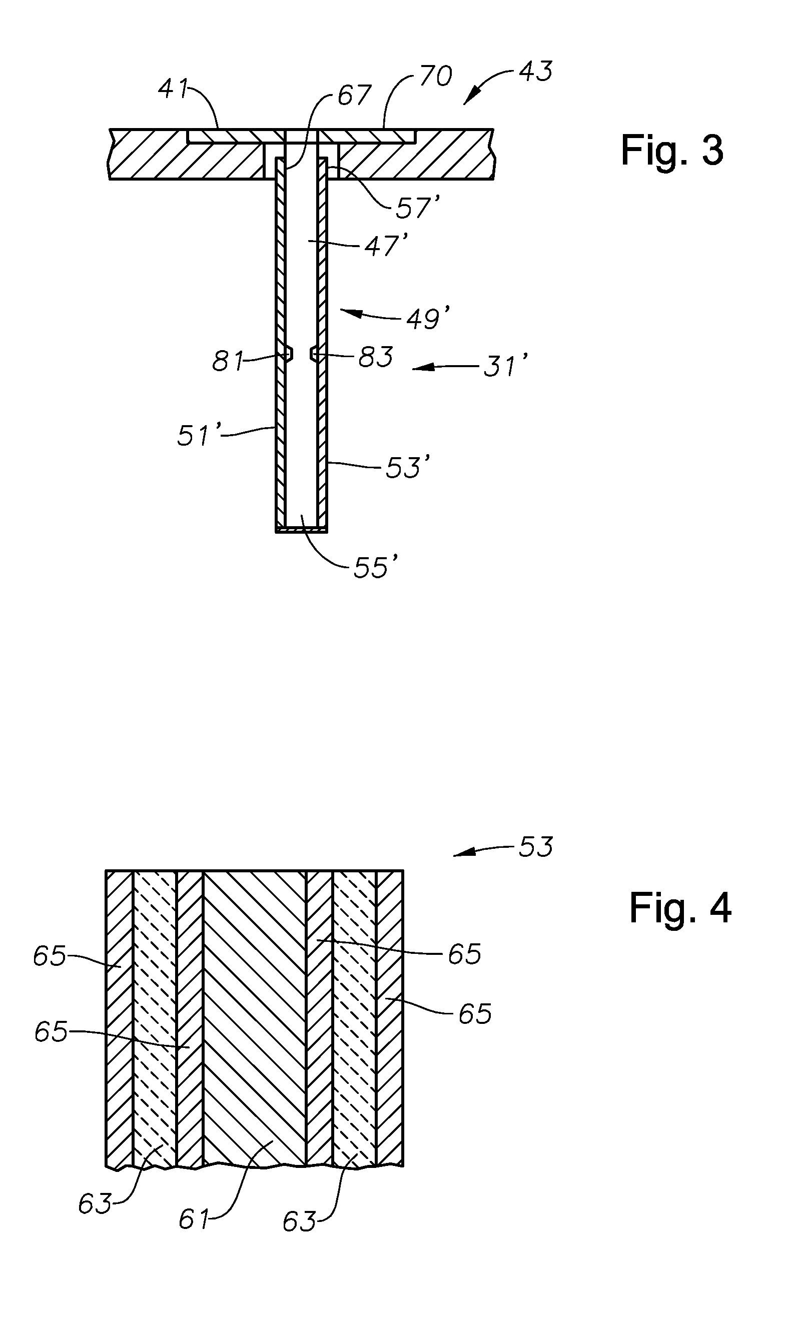
system includes a synthetic jet actuator including an actuator chamber extending between an inner surface of a first wall of a pair of opposing walls containing a pair of piezoelectric
layers forming a bimorph and an inner surface of a second wall also containing a pair of piezoelectric
layers forming a bimorph. The actuator chamber is dimensioned to expel a fluid through an associated chamber orifice responsive to electrical actuation of the first and the second walls resulting in complementary inward movement of at least portions of the walls toward a center of the chamber, and to receive a fluid responsive to outward movement of the at least portions of the first and the second walls away from the center of the chamber. The synthetic jet actuator also includes a first
electrode physically connected to the inner surface of the first wall and a second
electrode physically connected to the inner surface of the second wall and positioned adjacent the first electrode, ideally at or near a medial portion thereof, to provide for formation of an arc therebetween when subjected to a certain minimum electrical potential therebetween (e.g., determined based upon the expected type of environmental fluid and gap distance between electrodes) to thereby enhance fluid expulsion from the chamber.
[0019]As noted above, various embodiment of the present invention also include methods for controlling fluid flow utilizing one or more embodiments of a synthetic jet actuator and associated
system components. For example, a method of controlling fluid flow according to an exemplary embodiment of the present invention includes the steps of actuating a pair of opposing walls of a dual bimorph portion of a synthetic jet actuator configured to contract inwardly to expel a fluid from within a dual bimorph chamber or cavity formed at least partially by the opposing chamber walls to thereby provide flow control of an environmental flow. The method also includes forming an arc between a pair of opposing electrodes each separately connected to an inner surface of a different one of the opposing walls to enhance expulsion of the fluid from within the chamber when
performance enhancement or an extended operating margin is desired over that capable of being supplied by the dual bimorph portion (subsystem) of the synthetic jet actuator. In operation, to achieve the
performance enhancement and / or extended operating margin provided by the arc, a large
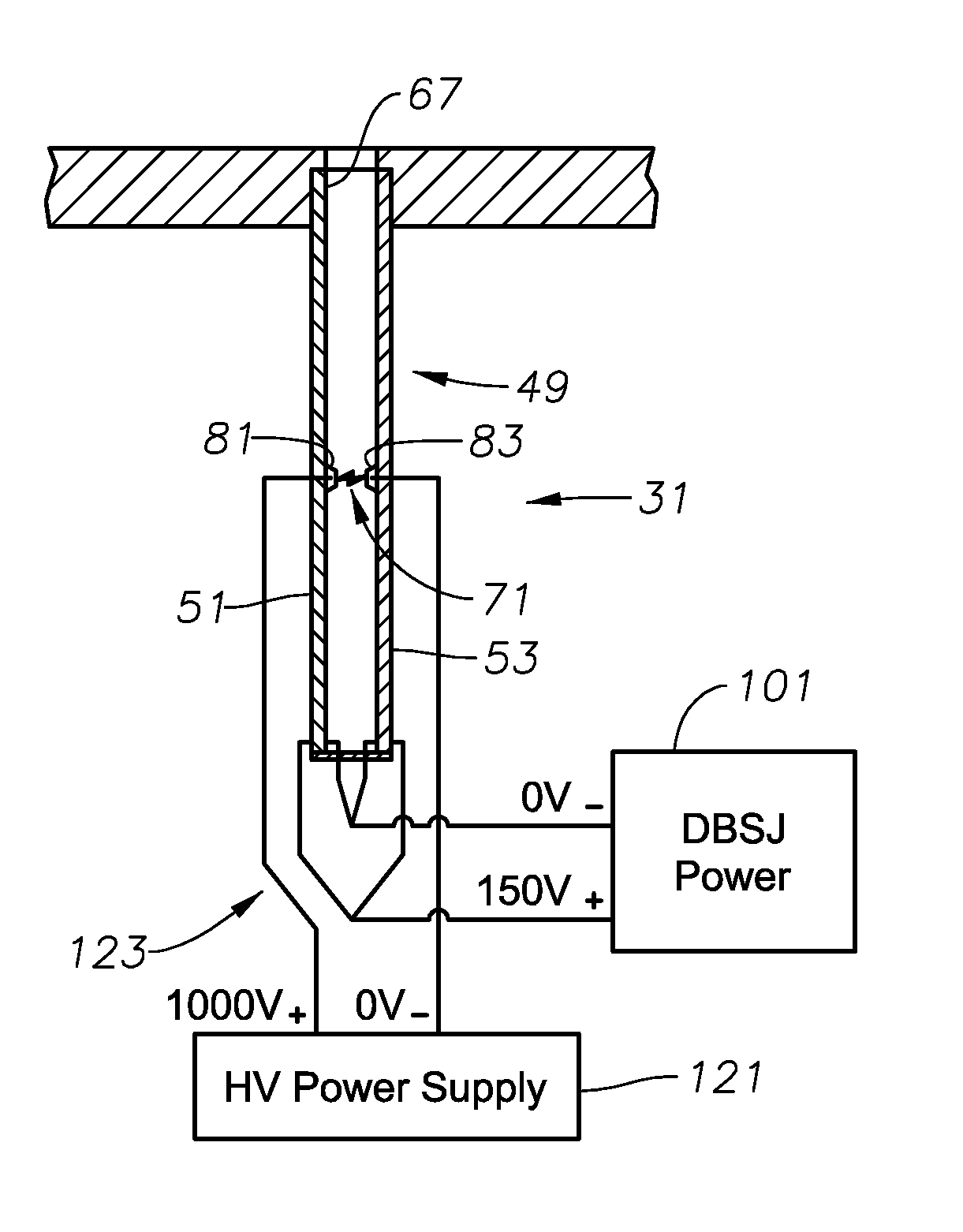
voltage potential is applied to the pair of opposing electrodes timed or otherwise oriented to the contraction of the dual bimorph portion of the actuator, which results in the arc passing through a portion of the chamber between the electrodes. The arc causes considerable heating of the localized gasses or other fluids within the chamber causing expansion of the fluids therein which leads to an enhanced (increased) exit velocity for the exiting synthetic jet, thus, extending the useful range of the synthetic jet actuator.
[0021]According to another embodiment of the method, the step of forming an arc includes, for example, the steps of setting one negative terminal of a first one of the pair of opposing walls to a low value such as, for example, 0 V, and setting the negative terminal of the second one of the pair of opposing walls initially to a low value such as, for example, 0 V, but then selectively switchably setting the voltage applied to the negative terminal of the second one of the pair of opposing walls to an offset base voltage of, for example, 1000 V to selectively form a voltage potential of 1000 V between electrodes, and thus, selectively form the arc. Advantageously, this procedure results in
selective control of
fluid temperature, pressure, and exit velocity of fluid from within the synthetic jet actuator chamber, effectively extending the performance and / or operating margin of the dual bimorph subsystem portion of the synthetic jet actuator.
[0022]According to another embodiment of the present invention, the step of actuating the pair of opposing walls to contract inwardly toward the center of the chamber includes the step of applying a voltage potential of, for example, 150 V to both the bimorph of the opposing walls to expel the fluid from within the synthetic jet actuator chamber. Correspondingly, the step of forming an arc includes the step of applying to the pair of electrodes, a voltage potential of, for example, 1000 V or other voltage potential sufficient to cause the fluid within the synthetic jet actuator chamber to break down to thereby enhance expulsion of the fluid within the chamber. According to a preferred implementation, the step is performed, for example, in response to detecting insufficient output from the synthetic jet actuator and / or receiving control signals indicating a desired level of fluid expulsion from the synthetic jet actuator chamber to thereby extend the performance and / or operating margin of the dual bimorph subsystem portion of the synthetic jet actuator.

