Unlock instant, AI-driven research and patent intelligence for your innovation.

Differential resonant ring oscillator utilizing magnetically tuned yig resonators to achieve ultra low phase noise and multi-octave electronic tuning in microwave frequencies

a technology of yig resonators and differential resonant ring oscillators, which is applied in the direction of oscillator generators, logic circuits, pulse generation, etc., can solve the problems of limiting the tuning bandwidth, limiting the rf current in the disclosed design, and reducing the quality factor (q). achieve ultra low phase noise, limit the tuning bandwidth, and achieve ultra broadband electronic tuning range

Active Publication Date: 2011-06-23
VIDA PRODS
View PDF4 Cites 2 Cited by
  • Summary
  • Abstract
  • Description
  • Claims
  • Application Information

AI Technical Summary

Benefits of technology

[0009]The present invention is a YIG tuned oscillator circuit that uses a differential gain topology that enables the oscillator to achieve an extremely broadband electronic tuning range while at the same time achieving ultra low phase noise. As a natural result of the differential circuit topology, reactive elements have been eliminated. This includes such things as tuning stubs that limit tuning bandwidth by contributing excessive open loop change in phase shift. The open loop phase shift of the differential oscillator is associated with completely non-dispersive circuit elements, such as the physical angle of the coupling loops, a differential loop crossover, and the high frequency phase shift of the amplifiers or gain stages. The differential gain topology also solves the major problem with the resonant ring oscillator previously patented in that parasitic RF currents can be prevented from coupling to resonators. When parasitic RF currents couple to the resonators they are superimposed on the desired currents resulting in degradation of quality factors (Q) due to magnetic field distortion or phase reversals which can stop oscillations. Specifically, all RF currents in the disclosed designs are confined to the desired coupling mechanisms. This common mode rejection approach will enable interface with existing Monolithic Microwave Integrated Circuit (MMIC) designs facilitating broad product usage.

Problems solved by technology

This includes such things as tuning stubs that limit tuning bandwidth by contributing excessive open loop change in phase shift.
When parasitic RF currents couple to the resonators they are superimposed on the desired currents resulting in degradation of quality factors (Q) due to magnetic field distortion or phase reversals which can stop oscillations.
Specifically, all RF currents in the disclosed designs are confined to the desired coupling mechanisms.

Method used


Image

  • Differential resonant ring oscillator utilizing magnetically tuned yig resonators to achieve ultra low phase noise and multi-octave electronic tuning in microwave frequencies
  • Differential resonant ring oscillator utilizing magnetically tuned yig resonators to achieve ultra low phase noise and multi-octave electronic tuning in microwave frequencies
  • Differential resonant ring oscillator utilizing magnetically tuned yig resonators to achieve ultra low phase noise and multi-octave electronic tuning in microwave frequencies

Examples


Embodiment Construction

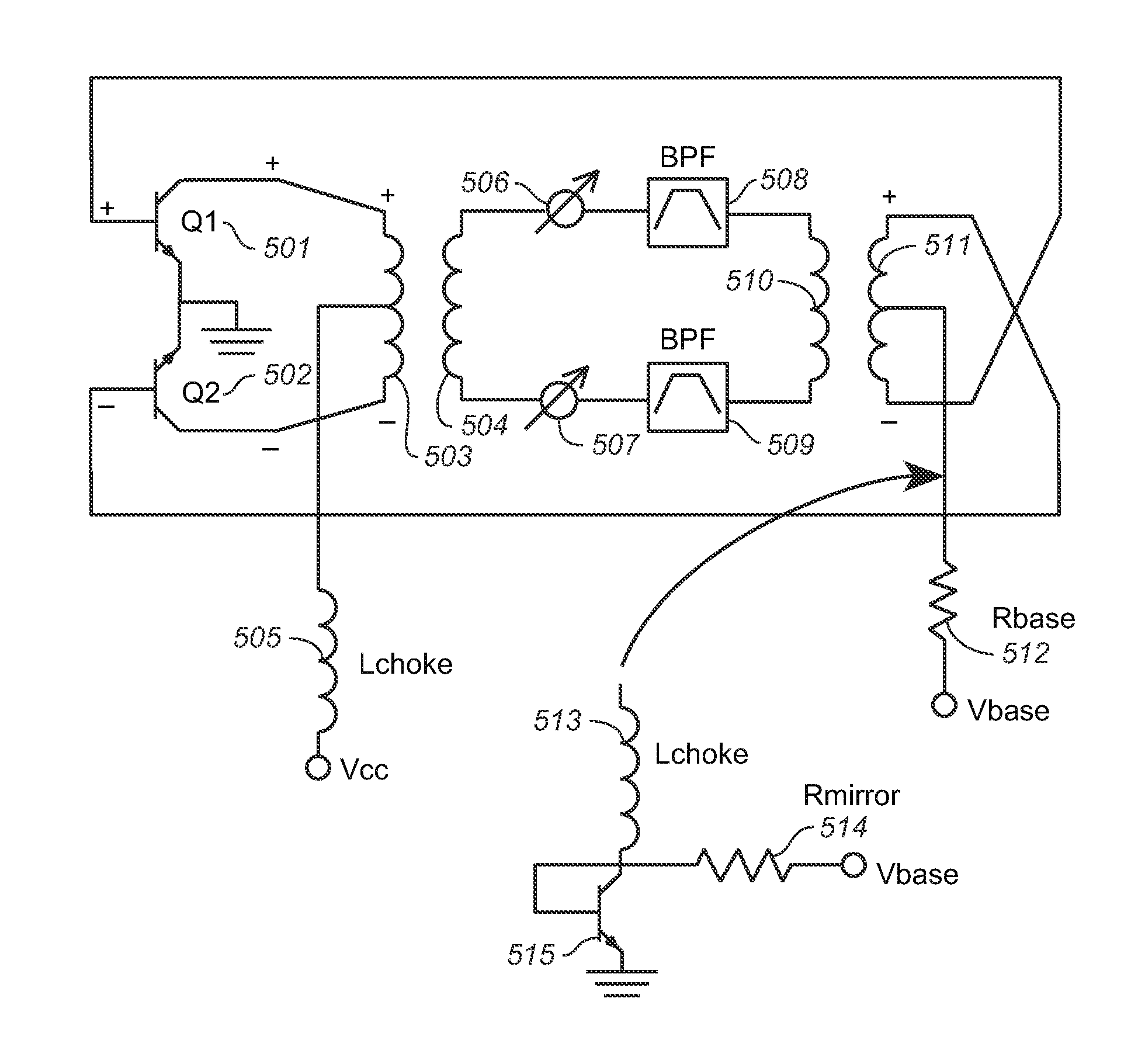
[0033]Referring to FIG. 1 a drawing is seen of a pair of coupling loops (preferably half turn) that transfer RF energy into and out of the YIG sphere. These loops provide a natural differential electrical interface to the rest of the oscillator's circuit. An equivalent circuit model for the pair of coupling loops (plus the YIG sphere) is constructed as a pair of transformers that are interconnecting two identical band-pass filters. The filter's pass-band peak is at the YIG sphere's resonant frequency, as determined by the DC magnetic field.

[0034]Still referring to FIG. 1, in the physical configuration, collector excitation loop 102 and base feedback loop 103 are physically oriented around YIG sphere 101.

[0035]Still referring to FIG. 1, it can be seen that equivalent electrical model of the arrangement has collector excitation loop 106 inducing energy into effective inductor 107, through effective band-pass filters 104 and 105, causing effective inductor 108 to generate energy that i...


PUM


Abstract

A differential resonant ring oscillator (“DRRO*) circuit using a ring oscillator topology to electronically tune the oscillator over multi-octave bandwidths. The oscillator tuning is substantially linear, because the oscillator frequency is related to the magnetic tuning of a YIG sphere, which has a resonant frequency equal to a fundamental constant multiplied by the DC magnetic field. The simple circuit topology uses half turn or multiple half turn loops magnetic coupling methods connecting a differential pair of amplifiers into a feedback loop configuration having a four port YIG tuned filter, thus creating a closed loop ring oscillator. The oscillator may use SiGe bipolar junction transistor technology and amplifiers employing heterojunction bipolar transistor technology SiGe is the preferred transitor material as it keeps the transistor's 1 / f noise to an absolute minimum in order to achieve minimum RF phase noise.

Description

BACKGROUND OF THE INVENTION[0001]1. Technical Field[0002]The present invention relates generally to oscillator circuits for high frequency sources, and more particularly to a differential resonant ring oscillator circuit using a ring oscillator topology to electronically tune the oscillator over multi-octave bandwidths[0003]2. Background Art[0004]The background art is aptly described in only a few relevant documents, which include patents issued to one of the inventors of the present invention; notably, U.S. Pat. No. 5,801,591 to Parrott, which teaches a multi-octave ferrite oscillator topology that utilizes transformer coupling to provide the proper phase shift in the feedback loop. A ferrite element is magnetically saturated to produce a magnetic resonance An active element provides real impedance and gain over a wide frequency range at an input port. The input port is electrically coupled to a first inductive coupling structure that is electrically coupled to an RF current source...

Claims


Application Information

Patent Timeline
IPC IPC(8): H03K3/03
CPCH03B5/1888
Inventor PARROTT, RONALD A.SWEET, ALLEN A.
Owner VIDA PRODS