Optical phase modulation method and apparatus for quantum key distribution

a phase modulation and optical phase technology, applied in the direction of digital transmission, secret communication, securing communication, etc., can solve the problems of increasing the instability of the optical interferometer, and increasing the difficulty of configuring the optical interferometer. , to achieve the effect of increasing instability and insertion loss, simplifying the configuration of the interferometer, and increasing the stability

Active Publication Date: 2011-06-23
ELECTRONICS & TELECOMM RES INST
View PDF4 Cites 26 Cited by
  • Summary
  • Abstract
  • Description
  • Claims
  • Application Information

AI Technical Summary

Benefits of technology

[0025]According to embodiments, when an optical phase modulator is arranged outside an optical interferometer, a configuration of an interferometer may be simplified, and it is easy to replace the optical interferometer with another interferometer having difference configuration. A path difference between two paths of an asymmetric optical interferometer may be easily set. Also, difficulties, such as extension of an optical path caused by the optical phase mo...

Problems solved by technology

When a path difference of an asymmetric optical interferometer of a transmitter and a path difference of the asymmetric optical interferometer of the receiver are the same, adjacent two probabilities among the four probabilities of existence of the single photon may overlap with each other and may cause interference.
When an optical modulator to which a pigtailed optical fiber is attached is inserted to the optical interferometer, a length of an optical path is extended and thus, instability of the optical interferometer may increase, and a configuration may become complex.
The optical interferometer may be configured based on a polarization-dependent feature of the planar lightwave circuit and thus, difficulty in config...

Method used


Image

  • Optical phase modulation method and apparatus for quantum key distribution
  • Optical phase modulation method and apparatus for quantum key distribution
  • Optical phase modulation method and apparatus for quantum key distribution

Examples


Embodiment Construction

[0039]Reference will now be made in detail to embodiments of the present invention, examples of which are illustrated in the accompanying drawings, wherein like reference numerals refer to the like elements throughout. Embodiments are described below to explain the present invention by referring to the figures.

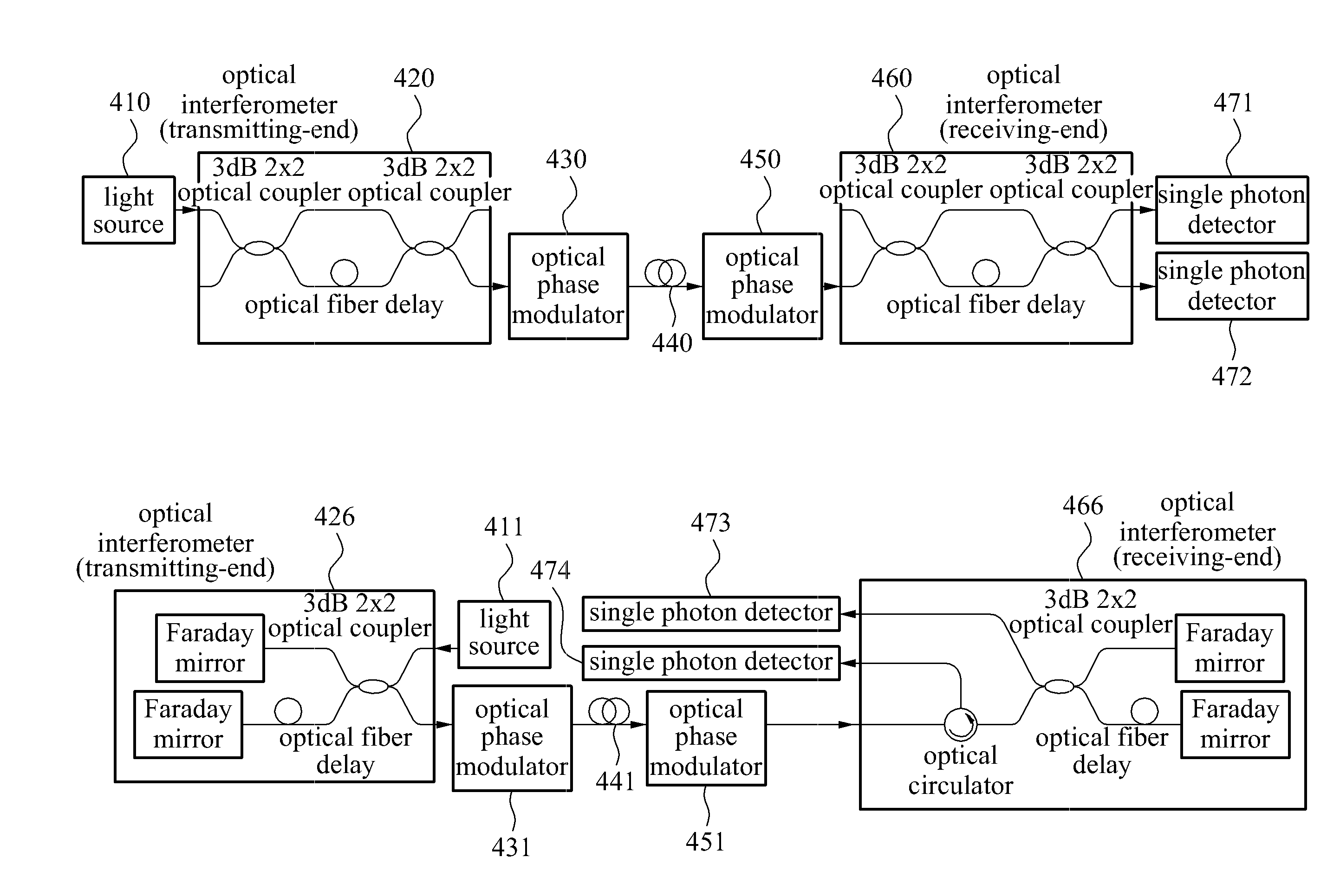
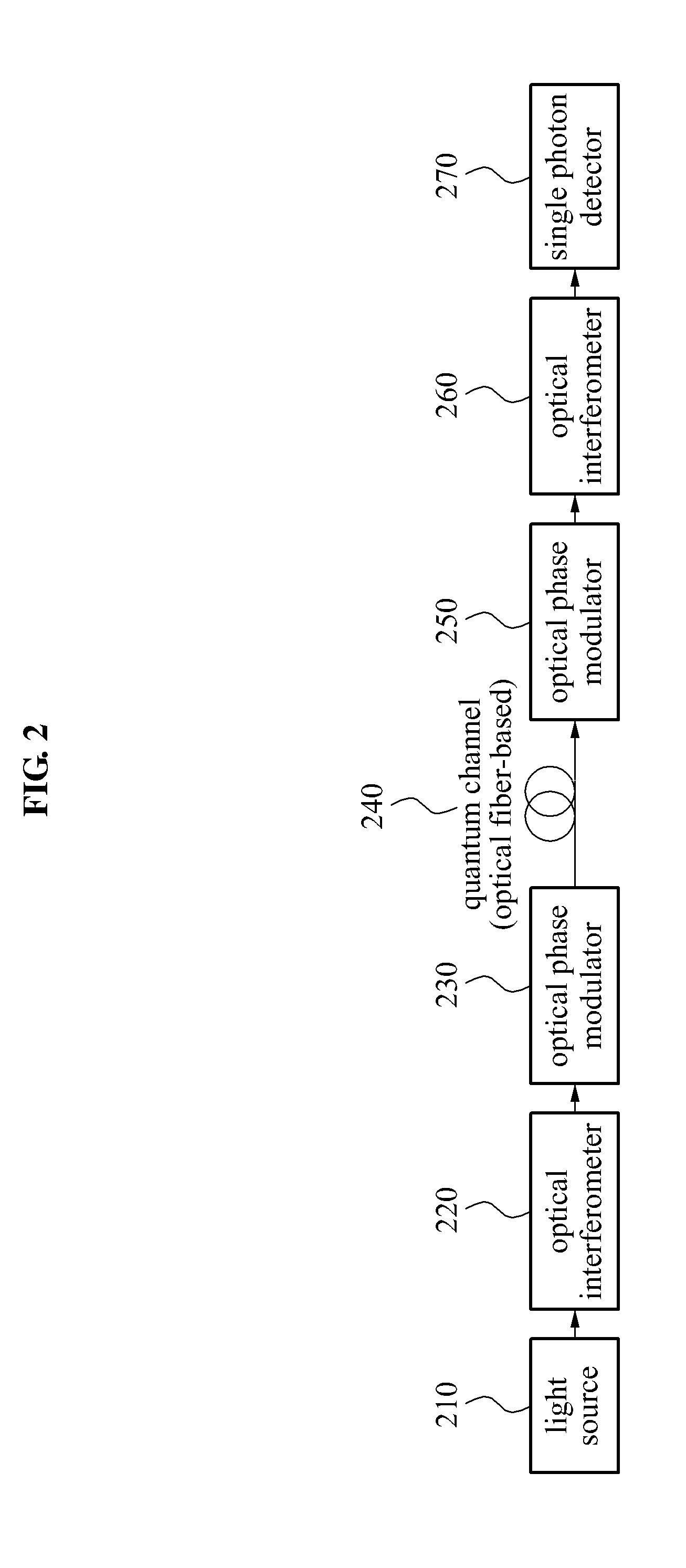
[0040]FIG. 2 illustrates a quantum key distribution system where an optical phase modulator is connected to an outside of an optical interferometer according to an embodiment of the present invention.

[0041]Referring to FIG. 2, a single photon from a light source 210 may be inputted to an optical interferometer 220, and a path may be divided to enable a probability of existence to be distributed in two different coordinates in a time domain. An optical phase modulator 230 being connected to an outside of the optical interferometer 220 may phase-modulate a single photon corresponding to one of the two coordinates. After the single photon is transmitted via an optical fiber-based...


PUM


Abstract

Provided is an optical phase modulating method and apparatus for a quantum key distribution. When an optical phase modulator is arranged outside an optical interferometer, a configuration of the optical interferometer may be simplified, and an extension of an optical path caused by the optical phase modulator, instability and an insertion loss increased in the optical interferometer, and the like, may be overcome. An output feature may be improved by adjusting an applied voltage of the optical phase modulator arranged outside the optical interferometer.

Description

CROSS-REFERENCE TO RELATED APPLICATION[0001]This application claims the benefit of Korean Patent Application No. 10-2009-0128456, filed on Dec. 21, 2009, in the Korean Intellectual Property Office, the disclosure of which is incorporated herein by reference.BACKGROUND[0002]1. Field of the Invention[0003]The present invention relates to a method that may arrange an optical phase modulator outside an interferometer and may modulate an optical phase in a phase modulation based quantum key distribution system.[0004]2. Description of the Related Art[0005]A quantum key distribution system may load key information on a single photon and may transmit the single photon to a receiver by adjusting a polarization or a phase of the single photon. A receiver may extract the key information using a polarization receiver, an optical phase modulator, and the like. The single photon transmission may be embodied based on optical communication technologies, and the quantum key distribution system inten...

Claims


Application Information

Patent Timeline
IPC IPC(8): H04L9/08
CPCH04L9/0858H04B10/70H04L9/08H04B10/548
Inventor CHO, JEONG-SIK
Owner ELECTRONICS & TELECOMM RES INST
Why Eureka
Try Eureka