System and method for interactive synchronized video watching

a video watching and interactive technology, applied in the field of compressed digital video delivery systems, can solve the problems of iptv and other packet network based video distribution systems suffering from both network delays and buffering delays, delay can be significant, and the type of overlay cannot control the delay to achieve the required synchronized watching, and achieves the effect of reducing frame rate, reducing signal to noise ratio, and reducing resolution

Inactive Publication Date: 2011-06-23
VIDYO
View PDF22 Cites 56 Cited by
  • Summary
  • Abstract
  • Description
  • Claims
  • Application Information

AI Technical Summary

Benefits of technology

[0041]While a classical digital video distribution system delivers full resolution video, the present invention uses the layered real-time codec. The video content displayed in the overlaid MBWs can use the lower layer(s) of the low delay and layered codec (representing lower resolutions, lower frame rate or lower signal to noise ratio) using much less bandwidth and enabling a low processing complexity, while the jointly watched video content can be delivered in full resolution but with low delay.

Problems solved by technology

These delays are caused by: (a) network delays due to varying route lengths between source and receiver, and (b) delays resulting from buffering by the decoder at the receiving end, which is necessary to alleviate the effects of: (i) delay jitter caused by varying queuing delays in transport network routers; (ii) packet losses in the network; and / or (iii) bandwidth changes in the transport network (such as variable link bandwidths experienced in wireless networks).
IPTV and other packet network based video distribution systems suffer from both network delays and buffering delays.
In the evolving IPTV environment, particularly where video is delivered over a best effort network such as the public Internet, where the network conditions are totally unpredictable, these delays can be significant (for example, up to a few tens of a second).
While it is possible to overlay a traditional streaming based video distribution system with a typical conferencing system to approximate the system disclosed in this invention, this type of an overlay cannot control delay to achieve the required synchronized watching.
(1) Maximum Delay Based Equalization: This method employs an out of band control layer, which measures the delay between the video source and each receiver in the group, and adjusts each receiver's display time according to the maximum delay. This method requires the measurement of all delays and a means for determining and distributing the value of the maximum delay to all participants throughout the session, because: (a) changing network conditions may result in changing delays as the video is being delivered, and (b) there may be new users with varying delays added to the group.
(2) Longest Route Delay Based Equalization: With this technique, the video source sends the same video to each receiver, but along network routes that give essentially the same amount of delay (if there are multiple routes available for each receiver). For example, when the video source is in New York, and there are two users in New York and two users in California, the computation of route lengths results in serving the users in New York using a longer route, for example, through Atlanta and back to New York, to attain the same geographical distance between the video source in New York and users in both New York and California. This method may not be practical where no such equalizing routes are available. Even where such routes are available, the system uses the network inefficiently by selecting long routes for receivers that are closer to the video source, and it is very difficult, if not impossible, to deal with path delay variations.
Although the above described methods or similar techniques can be used to equalize the network delay in a streaming based video distribution system, receiver side buffering delay can be even more significant.
Network-triggered error conditions can occur due to congestion, even when transport delays are equalized or non-existent.
Although the largest receiver buffer size can be communicated to all receivers (similar to maximum network delay based equalization) so that each receiver delays its display until the receiver with the largest buffer can display the video, none of these systems can be used for live interaction among video watchers.
However, given that transport delays are usually the biggest component of delay, a generic video teleconferencing codec does not alleviate the delay problems altogether.
These techniques eliminate the need for any buffering at the receiver by introducing slight performance degradation in the event of packet loss or excessive packet delay.
A limitation of single layer coding exists where a lower spatial resolution is required, such as a smaller frame size.
The full resolution signal must be sent and decoded at the receiving end, thus wasting bandwidth and computational resources, with downscaling performed at the receiver or at a network device.
Losses in the enhancement streams will result in a graceful degradation of picture quality.

Method used


Image

  • System and method for interactive synchronized video watching
  • System and method for interactive synchronized video watching
  • System and method for interactive synchronized video watching

Examples


Embodiment Construction

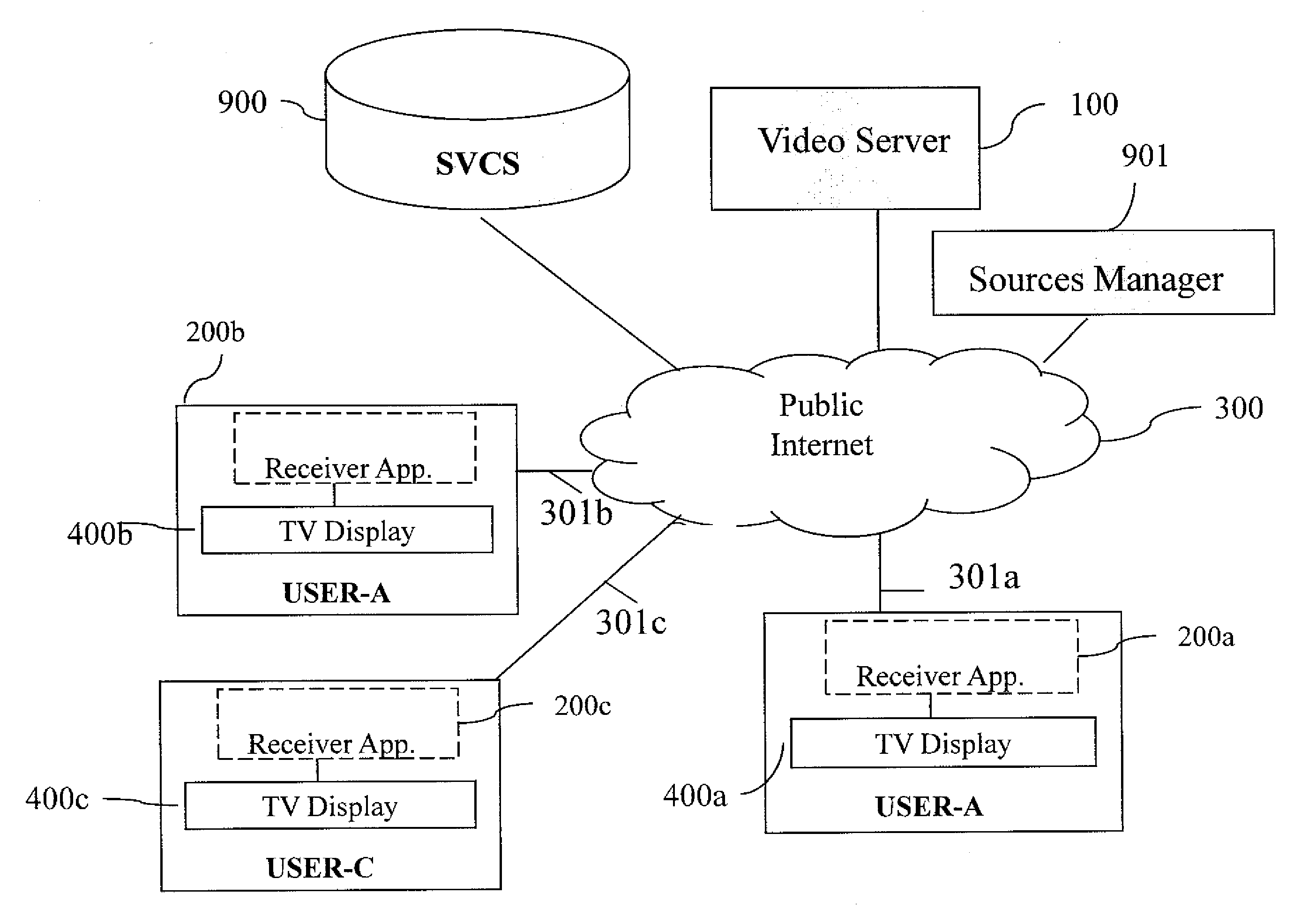
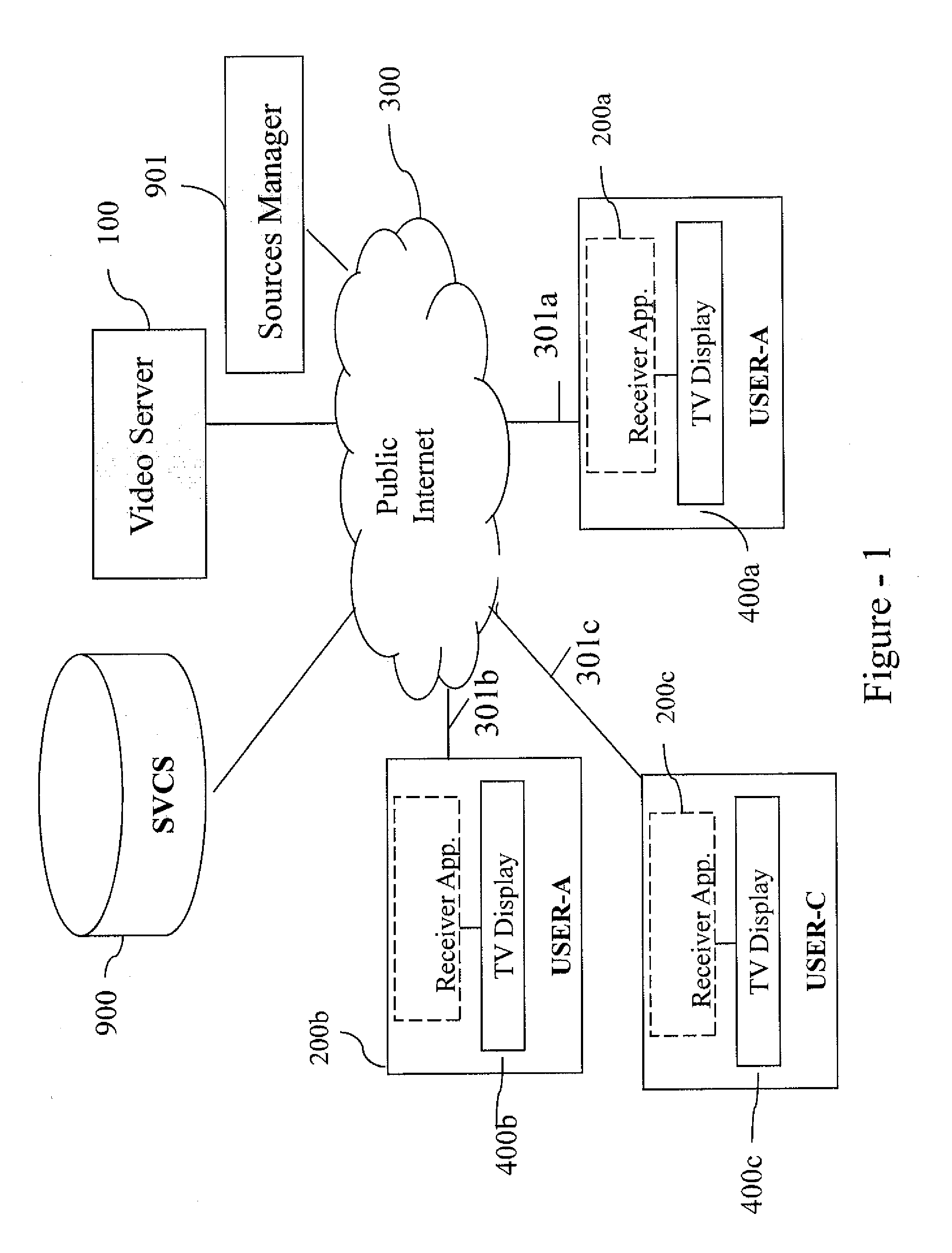
[0054]FIG. 1 illustrates an exemplary system for interactive synchronized video watching using a video server and an overlay conferencing system. The system comprises a video server 100, which contains one or more physical servers, located at the IPTV provider's network, the receiver application 200a, 200b or 200c at each TV user's location, alternatively known as the user or client, and public Internet 300, interconnecting video server 100 to receiving application 200a, 200b or 200c. While the network illustrated in FIG. 1 is the Public Internet 300, the present invention also envisions that the video server 100 and receiving application 200a, 200b or 200c can communicate over another network, for example, another IP network, a packet network, a combination of a private IP network and public Internet, or a private network, depending on the service provider's network architecture choice.

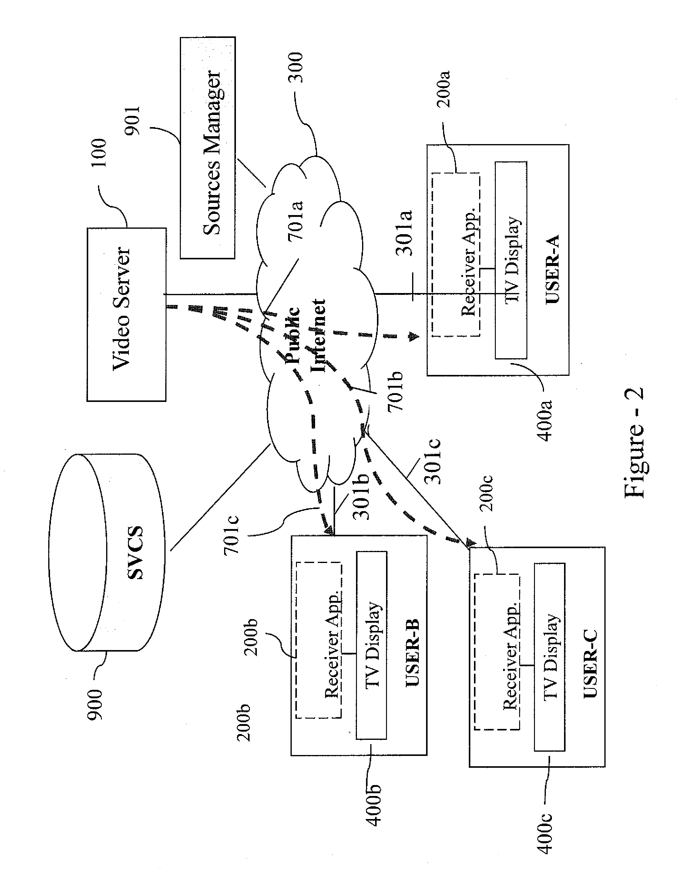
[0055]In an exemplary embodiment for interactive synchronized video watching, the system has one ...


PUM


Abstract

The present invention provides techniques for digital video distribution that provides for joint video content watching amongst a group of watchers using multiple mini browsing windows (MBWs), such that the watchers can simultaneously interact with each other in a video conferencing-like setting (i.e., seeing selected watchers' videos in MBWs and hearing their voices) while they view together specific video content in a synchronized way. The MBWs can be displayed as overlays on the main video window being watched on full screen.

Description

CROSS-REFERENCE TO RELATED APPLICATIONS[0001]This application claims the benefit of priority to U.S. Provisional Application Ser. No. 61 / 289,249, filed Dec. 22, 2009, which is hereby incorporated by reference herein in its entirety.BACKGROUND[0002]1. Technical Field[0003]The present invention relates to compressed digital video delivery systems such as cable TV (CATV), satellite TV, Internet protocol TV (IPTV) and the Internet based video distribution systems. In particular, it relates to the use of a low-delay and layered codec and the corresponding low-delay transport, typically used for video-conferencing systems. The disclosed digital video delivery system allow a group of watchers to watch one or several selected video content in such a way that the video is synchronously displayed regardless of location and network bandwidth.[0004]2. Background Art[0005]Subject matter related to the present application can be found in U.S. patent application Ser. No. 12 / 015,956, filed and enti...

Claims


Application Information

Patent Timeline
Patent Type & Authority Applications(United States)
IPC IPC(8): H04N7/173
CPCH04N7/15H04N7/173H04N21/4788H04N21/4223H04N21/4312H04N21/242
Inventor CIVANLAR, REHASHAPIRO, OFERLEVY, ISAACSHALOM, TAL
Owner VIDYO
Why Eureka
Try Eureka