Gearbox Assembly for an Electric Power Steering System

a technology of electric power steering and gearbox, which is applied in the direction of gearbox assembly, mechanical equipment, transportation and packaging, etc., can solve the problem of backlash between non-torque-transmitting parts, given space, etc., and achieve the effect of convenient packaging of the gearbox assembly

Active Publication Date: 2011-06-30
TRW AUTOMOTIVE US LLC
View PDF4 Cites 22 Cited by
  • Summary
  • Abstract
  • Description
  • Claims
  • Application Information

AI Technical Summary

Benefits of technology

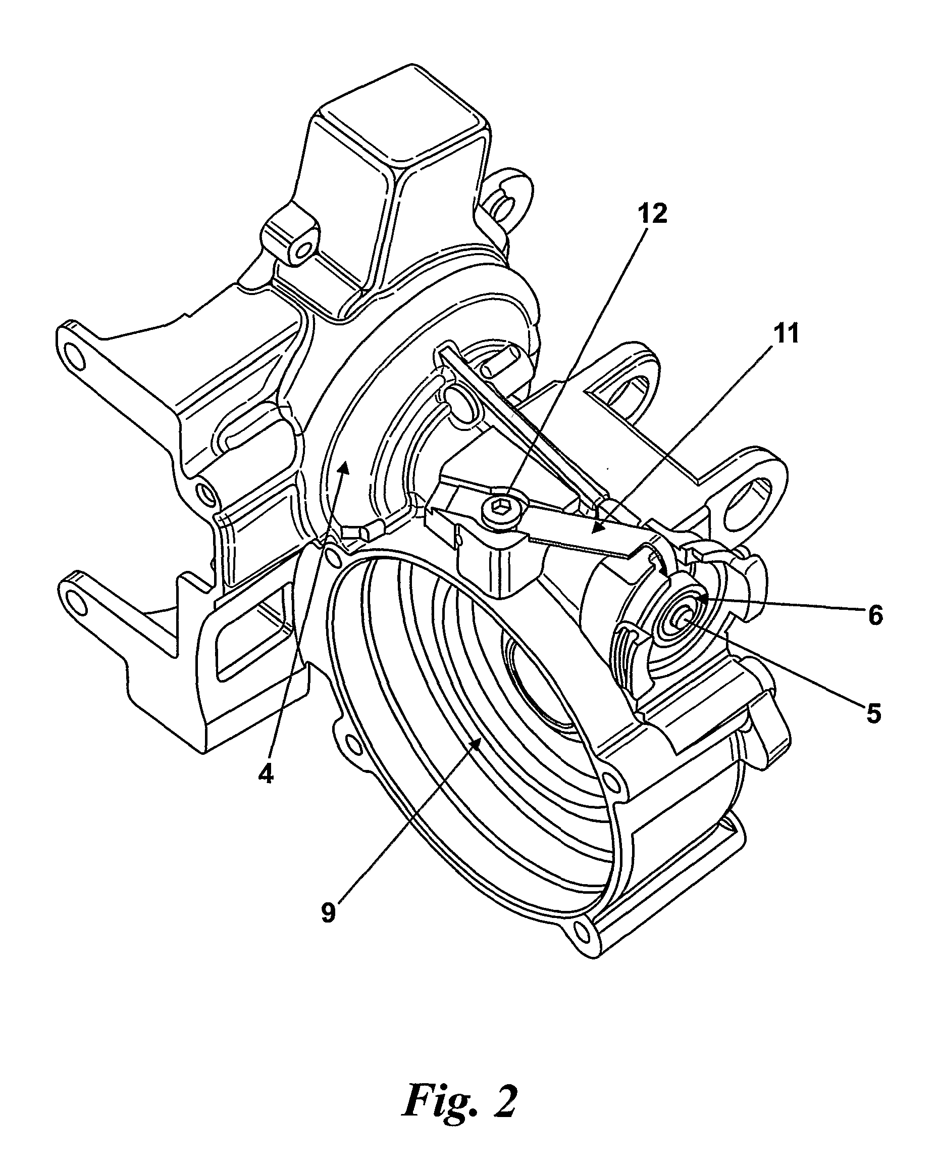
[0019]To provide the higher spring rate for movement in the second direction away from neutral and to provide the step change in spring rate, an abutment which functions as a fulcrum may be provided which contacts the leaf spring between the point where it is fixed to the housing and the tip of the spring. As the spring is moved in the second direction towards and then past the neutral position the leaf arm will contact the abutment. This effectively means that only a much shorter length of arm is available to bend giving the effect of a shorter leaf spring with a naturally higher spring rate. The use of a fulcrum is especially suitable for the generation of a step change in spring rate with a simple leaf spring.
[0021]Alternatively, the fulcrum may be spaced slightly from the leaf spring in the neutral position. This allows a small amount of movement in the second direction at the lower spring rate associated with movement in the first direction away from neutral before the higher spring rate comes in to play. This may be useful in allowing for a small amount of movement of the bearing in the second direction away from the neutral position due to eccentricity in the bearing or shaft or worm or misalignment of parts to be accommodated with a constant (or nearly constant) biasing force.
[0022]The fulcrum may be substantially rigid so that it does not move or deform when the leaf spring presses against it. Alternatively the fulcrum may be resilient so that it compresses when pressed by the leaf spring. This gives a secondary spring force which may allow more fine tailoring of the spring rate for movement in the second direction away from the neutral position.
[0023]The abutment may contact the L-shaped spring at a point approximately midway along the length of the arm that is fixed to the housing (i.e. midway between the fixing point to the housing and the bend in the spring). It may contact the spring closer to the fixed end than this or closer to the bend. For example, it may be located one third along from the fixed end or free end. Placing the fulcrum closer to the bend may produce a much greater spring rate for movement in the second direction away from the neutral position compared with a placement closer to the fixed end.
[0028]The position of the abutment relative to the housing, and also relative to the leaf spring, may be adjustable. This allows the leaf spring to be set to give the desired bias to the bearing during manufacture and the abutment to be positioned accurately relative to the leaf spring. In this way the position of the step change in spring rate can be adjusted and accurately controlled.
[0035]It will be appreciated that other spring assemblies could be used which do not rely on leaf springs. A leaf spring is preferred because it is almost flat, apart from the tip that projects into the housing which makes packaging of the gearbox assembly easier where space constraints exist.

Problems solved by technology

Therefore, greater gear wheel torque is needed to cause a given amount of space (backlash) to appear between the non torque-transmitting (i.e. non-contacting) flanks of the worm and gear teeth.
Any movement of this kind is usually due to eccentricity of the worm or wheel or wear of the teeth or bearings over time.

Method used


Image

  • Gearbox Assembly for an Electric Power Steering System
  • Gearbox Assembly for an Electric Power Steering System
  • Gearbox Assembly for an Electric Power Steering System

Examples


first embodiment

[0066]As shown in FIG. 5, an abutment 31 is incorporated into a Bearing Cover Plate 13 whose other functions include sealing the aperture 14 in the housing 4. The Plate 13 is fixed to the housing by screws 15 which pass through oval holes 16 in the Plate. These holes allow the plate to be moved a small distance (vertically in FIG. 5) either side of its nominal position, while the screws are still loose. This enables the abutment 31 to be brought into light contact with the spring 11, as described in the preceding description of the basic invention. It is envisaged that control of this process would be optimised, in a mass-production facility, by an automated method of positioning the plate relative to the spring and, almost simultaneously, temporarily clamping the plate relative to the housing by an auxiliary device so that the chosen position is not disturbed by the subsequent tightening of the screws. The plate is guided against rotation by the engagement of two accurate slots 17 ...

second embodiment

[0067]In an alternative embodiment shown in FIG. 6, an alternative abutment 40 is formed by the central portion of a bent rod 41 in which legs 42, 43 are formed at right-angles to either side of the said central portion. The legs of the rod are located in parallel holes 44, 45 in the housing 4. At least one threaded hole 46 in the housing intersects at least one of the holes 44 so that a screw 47 can be inserted in said hole and used to retain the rod 41 in a fixed position relative to the housing once the said screw 47 has been tightened. The screw 47 may be a headed screw as shown in FIG. 6c or it may be a grub screw. The screw 47 may be further secured by using a lock-nut (not shown) and / or by the application of an adhesive to either the male and / or the female thread. The rod is prevented from rotating about an axis parallel to its legs by having a pair of said legs which are distal from one another and which locate in the pair of holes 44, 45 in the housing. Alternatively, one l...

third embodiment

[0069]Referring to FIG. 7(a) to (d), an abutment 50 is formed by a deposit of a resin-like material which is dispensed in liquid form into the gap between the spring 11 and an adjacent and substantially parallel surface 51. The said surface is that of a relatively stiff part 52 which is fixed to the gearbox housing 4. For example the said part 52 could be attached to the housing 4 by at least one screw 53 which engages with at least one threaded hole 54 in the housing. Alternatively, the said surface 51 could be an extension of the housing 4 itself. The gearbox is assembled and run-in prior to the material being dispensed or at least prior to it hardening. The material 55 may be one that cures to a relatively rigid state or alternatively one that sets to a defined elasticity. In the latter case, the said defined elasticity will influence the effective rate that the spring acquires after the curing process and therefore should be taken into account when deciding the position of the a...


PUM


Abstract

A gearbox assembly for all electric power steering apparatus comprises an input shaft which carries a worm gear and is supported relative to the housing at one end by a first bearing assembly and at the other by a second bearing assembly, an output shaft which carries a wheel gear which is fixed relative to a housing and which meshes with a worm gear on the input shaft, and a spring assembly which acts between the housing and the first bearing assembly, and the spring assembly applying a biasing force onto the second bearing in a first direction away from the neutral position so as to ensure that the worm and wheel are fully engaged. The spring assembly has a spring rate which has a step change about the neutral position such that the rate of change in the force exerted by the spring assembly on the second bearing assembly as the spring moves in the first direction from its neutral position is lower than the rate of change in the force as the spring moves in the second direction away from the neutral position.

Description

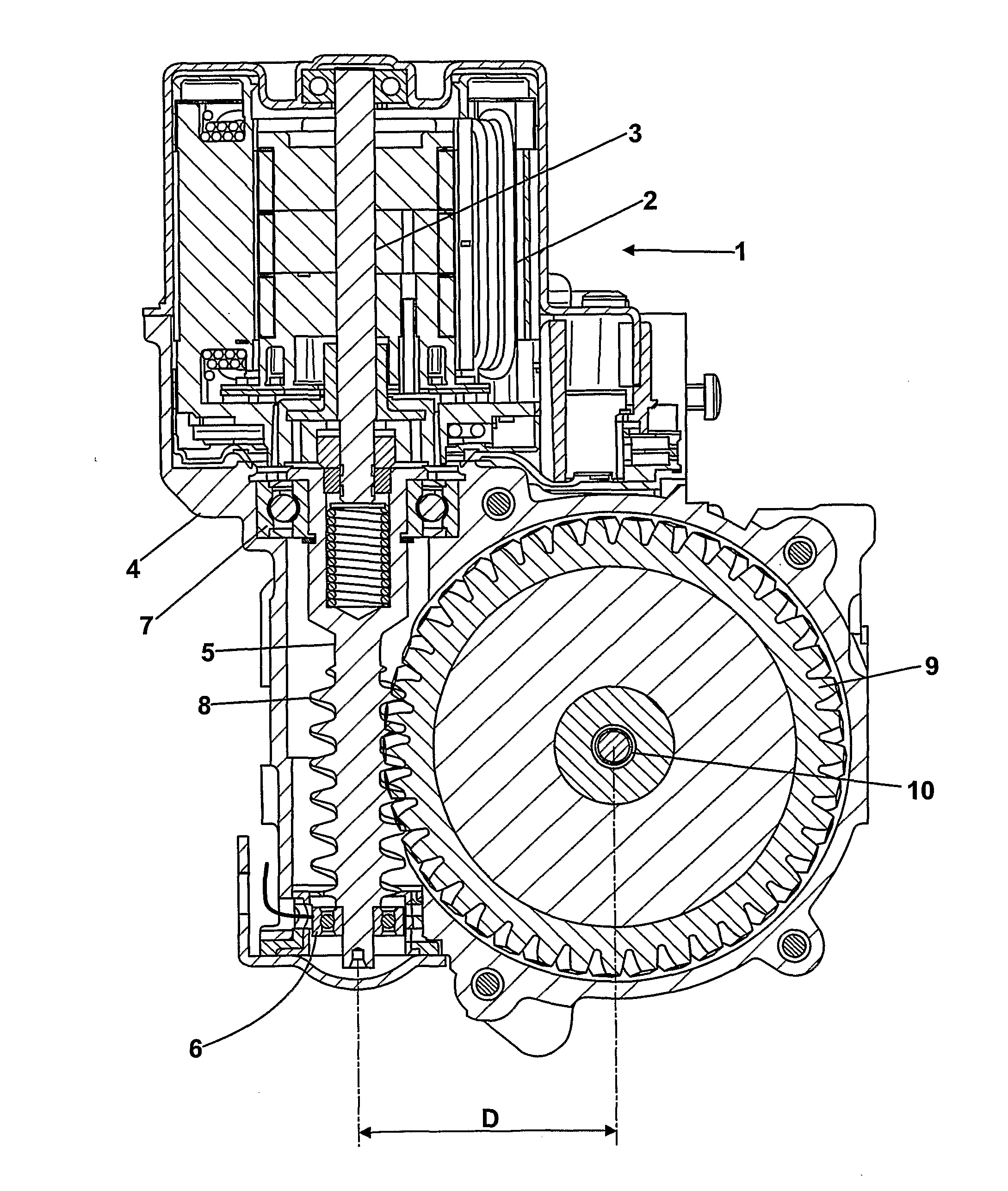
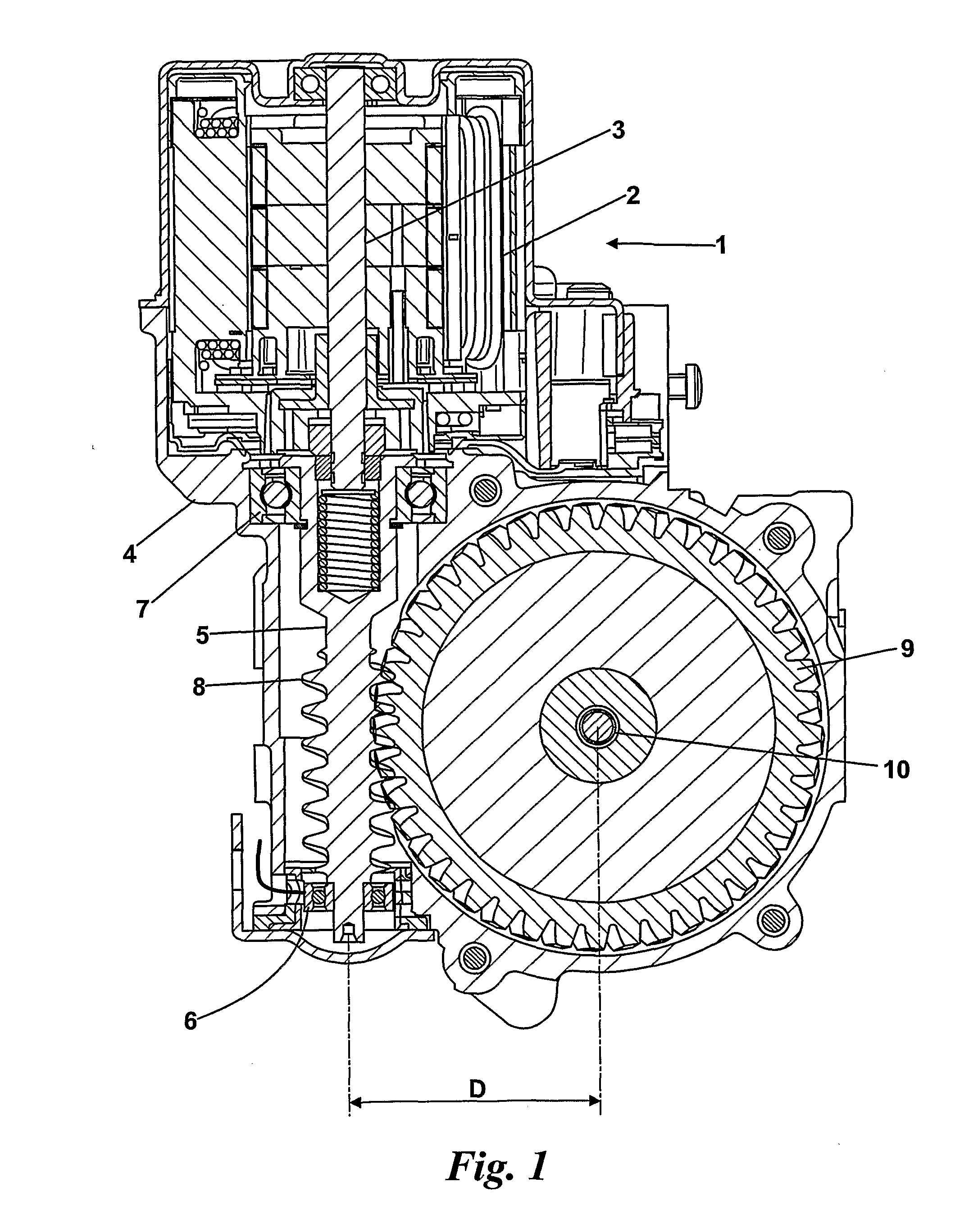
CROSS-REFERENCE TO RELATED APPLICATIONS[0001]This application is a national stage of International Application No. PCT / IB2009 / 052017 filed May 14, 2009, the disclosures of which are incorporated herein by reference in entirety, and which claimed priority to Great Britain Patent Application No. 0808795.9 filed May 15, 2008, the disclosures of which are incorporated herein by reference in entirety.BACKGROUND OF THE INVENTION[0002]This invention relates to improvement in gear assemblies, and in particular to power assisted steering assemblies which incorporate a worm and wheel gear assembly for transferring torque from an electric motor to a steering column or output shaft operatively connected thereto.[0003]It is known to provide a power steering system for a vehicle comprising an electric motor having a stator and a rotor, an input shaft operatively connected to the rotor and adapted to rotate therewith, an output shaft associated with a steering column, and a gearbox adapted to tran...

Claims


Application Information

Patent Timeline
Patent Type & Authority Applications(United States)
IPC IPC(8): B62D3/04B62D5/04
CPCB62D5/0409F16H2057/0222Y10T74/19898Y10T74/19828F16H2057/0213F16H55/24
Inventor WILKES, MARK ANTHONYAPPLEYARD, MICHAELWALSH, MICHAEL JAMES
Owner TRW AUTOMOTIVE US LLC
Why Eureka
Try Eureka