Aft pylon fairing for an aircraft engine suspension system

a technology of aircraft engine and suspension system, which is applied in the direction of digestive system, power plant arrangement/mounting, cardiovascular disorder, etc., can solve the problems of high thermomechanical stress within the deck and the side panels, obvious unfavorable elements of these elements, and deformation, etc., to reduce the thermomechanical stress applied, reduce the aerodynamic quality of the deck, and reduce the deformation

Active Publication Date: 2011-06-30
AIRBUS OPERATIONS INC AS A
View PDF6 Cites 45 Cited by
  • Summary
  • Abstract
  • Description
  • Claims
  • Application Information

AI Technical Summary

Benefits of technology

[0020]One of the specific features of this invention is the fact that this deck is now offset from the inner cross ribs by means of longitudinal walls, it being understood that these are the same walls that indirectly (and preferably alone) are used for assembly of the deck onto the ribs. In other words, the deck is no longer mounted on the ribs directly, which advantageously allows the deck to deform more freely due to thermal expansion following the large amount of heat released by the core engine flow delimited by this deck.
[0038]It is even further increased because the lack of embedment of the deck into the side panels advantageously prevents these side panels from being stressed and deformed, which could occur following deformation of the deck due to thermal expansion. In this respect, note that the side panels are immersed in the fairly cool fan flow, such that they experience very little deformation due to thermal expansion. Thus, their global deformation level is kept relatively low, which induces a very satisfactory aerodynamic quality participating in reducing parasite drag effects and improving the performance / consumption ratio of the aircraft.

Problems solved by technology

In this configuration the heat protection deck is in contact with the very hot core engine flow, which means that it deforms strongly due to thermal expansion.
However, its corresponding embedments into the inner cross ribs and into the lower end of each of the two side panels create high thermomechanical stresses within the deck and the side panels, which is obviously not good for these elements.
Nevertheless, they are affected by significant deformation caused by the stresses set up resulting from the expansion of the deck to which they are directly and rigidly connected, which degrades their aerodynamic shape and more generally deteriorates the global aerodynamic quality of the fairing.
Naturally, such degradation increases the generated parasite drag.
Since the core engine flow is a very fast jet, local deformations encountered at the deck create a fairly large parasite drag.

Method used


Image

  • Aft pylon fairing for an aircraft engine suspension system
  • Aft pylon fairing for an aircraft engine suspension system
  • Aft pylon fairing for an aircraft engine suspension system

Examples


Embodiment Construction

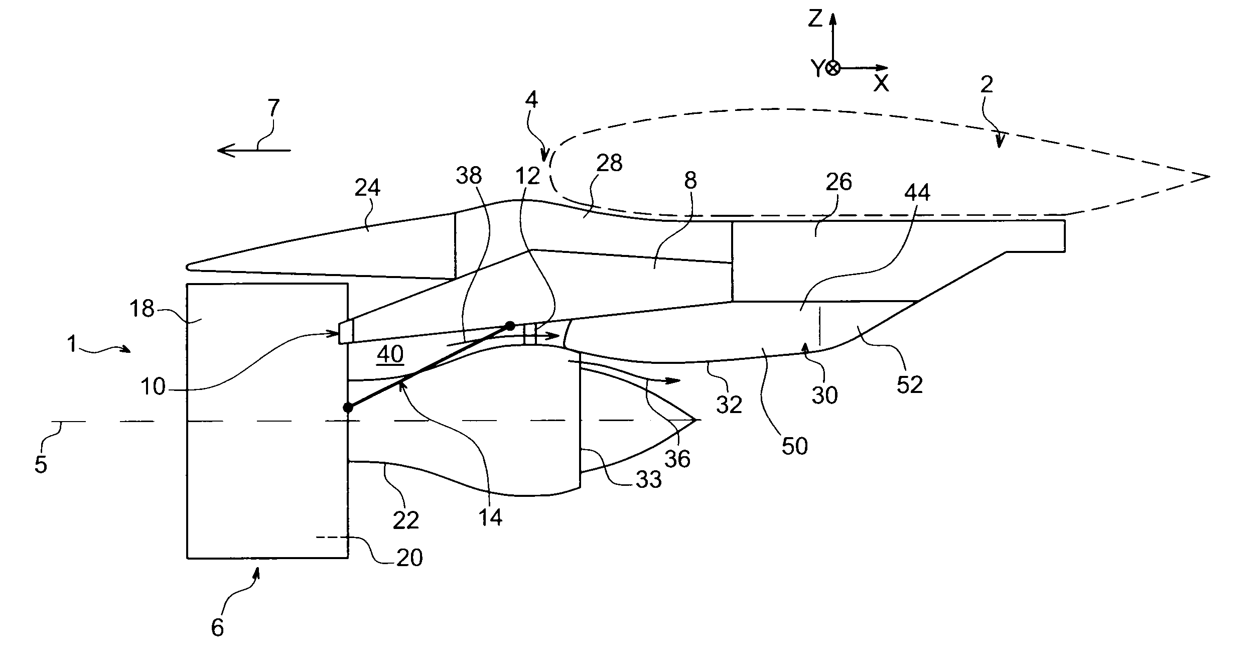
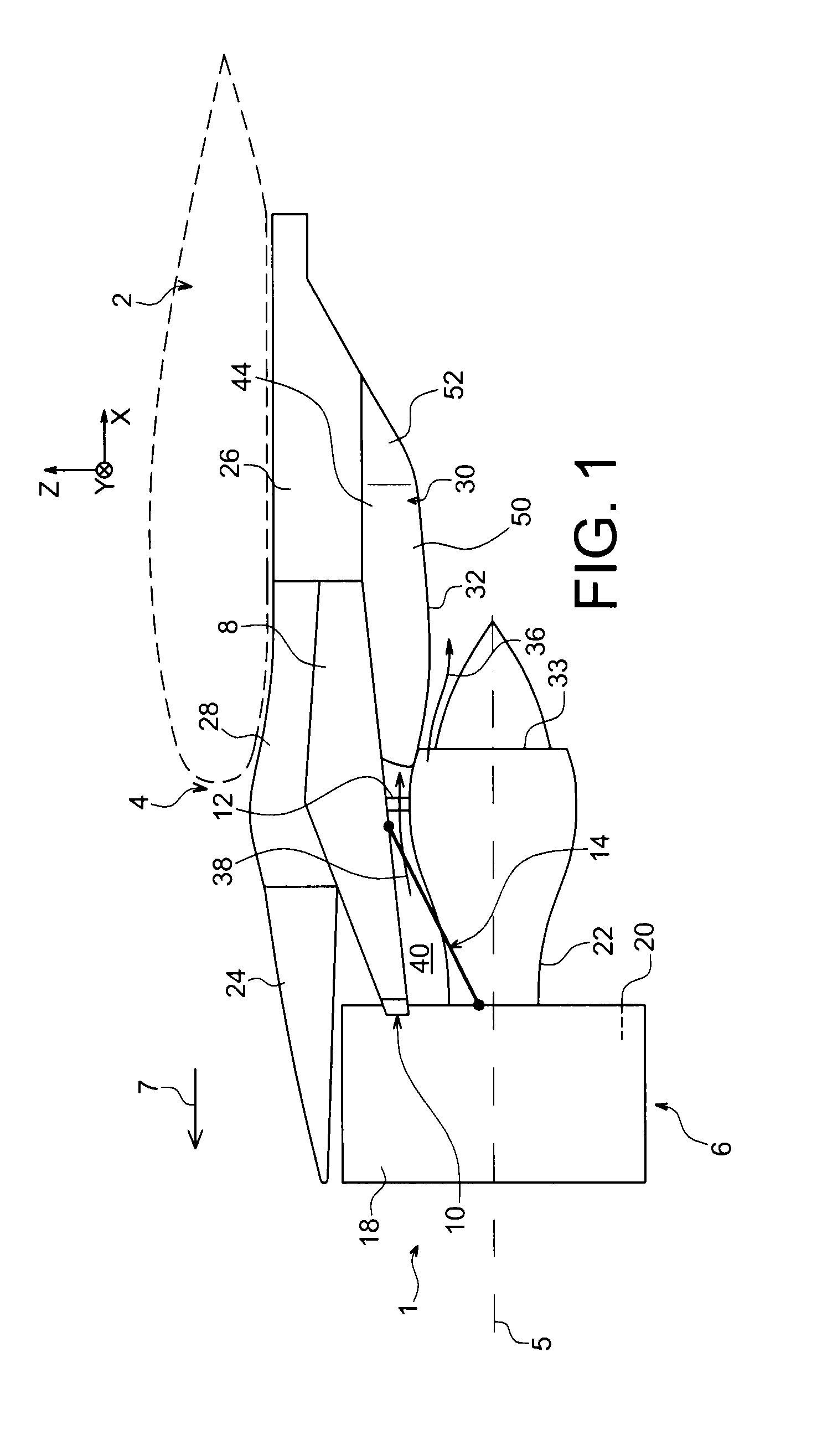
[0054]FIG. 1 shows an aircraft engine assembly to be fixed under a wing 2 of this aircraft, this assembly comprising a suspension system 4 according to a preferred embodiment of this invention, and an engine 6 such as a turbojet suspended under this system 4.

[0055]Globally, the suspension system 4 comprises a rigid structure 8, also called the primary structure, carrying the suspension means for the engine 6, these suspension means being provided with several engine suspensions 10, 12, and a system 14 for resisting thrusts generated by the engine 6.

[0056]Note that the assembly 1 will be surrounded by a nacelle (not shown) and that the suspension system 4 comprises another series of suspensions (not shown) added onto the rigid structure 8 and that suspend this assembly 1 under the aircraft wing 2.

[0057]Throughout the following description, by convention, X is the longitudinal direction of the system 4 and is also effectively the longitudinal direction of the turbojet 6 and the aft py...


PUM


Abstract

This invention relates to an aft pylon fairing (30) for a suspension system of an aircraft engine, comprising two side panels (44) assembled to each other by inner cross stiffening ribs (46) spaced at intervals from each other along a longitudinal direction (X) of the fairing, and also comprising a heat protection deck (32) designed to delimit an engine core flow (36). According to the invention, it also comprises two longitudinal connecting walls (58) offsetting the deck (32) from the ribs (46), each of these two longitudinal walls (58) being provided with a first side end (62) fixed to one or the other of the two side ends (60, 60) of the deck (32), and a second side end (64) rigidly fixed to the ribs (46).

Description

TECHNICAL DOMAIN[0001]This invention relates to an aft pylon fairing for an engine suspension system designed to be inserted between an aircraft wing and the engine concerned.[0002]The invention may be used on any type of aircraft fitted with turbojets or turboprops.[0003]This type of suspension system, also called an <<EMS>> (Engine Mounting Structure), can be used to suspend a turbo-engine below the aircraft wing, or to mount this turbojet above this wing.STATE OF PRIOR ART[0004]Such a suspension system is designed to form the connecting interface between a turbo-engine and a wing of the aircraft. It transmits forces generated by the associated turbo-engine to the aircraft structure, and also is used to route fuel, electrical and hydraulic and air systems between the engine and the aircraft.[0005]The suspension system comprises a rigid structure also called the primary structure, often a <<box>> type structure, in other words formed by the assembly of lower...

Claims


Application Information

Patent Timeline
Patent Type & Authority Applications(United States)
IPC IPC(8): B64D27/26B64D27/00B64D29/00B64C1/38
CPCB64D33/04B64D29/02A61P1/00A61P9/00A61P9/10A61P11/00A61P11/06A61P19/02A61P25/00A61P25/08A61P25/18A61P25/22A61P25/24A61P25/28A61P27/02A61P29/00
Inventor JOURNADE, FREDERICRENAUD, ERICJALBERT, DELPHINE
Owner AIRBUS OPERATIONS INC AS A
Why Eureka
Try Eureka