Ion detecting apparatus and ion generating apparatus

a technology which is applied in the field of generating apparatus and detecting apparatus, can solve the problems of small effect of eliminating virus and odor attached to curtains, clothes and the like, and the decrease in the amount of generated ions cannot be avoided, so as to increase the sterilization effect of virus, and reduce the possibility of being infected with virus

Active Publication Date: 2011-06-30
SHARP KK
View PDF12 Cites 13 Cited by
  • Summary
  • Abstract
  • Description
  • Claims
  • Application Information

AI Technical Summary

Benefits of technology

[0082]According to the present invention, one motor rotates two impellers, while the air generated by the rotation of each impeller is discharged to the outside from two air-flowing paths, in which ion generating sections are respectively arranged, so that ion concentration of ions discharged in a room together with the air can be increased. Hence, the sterilization effect of virus can be increased, reducing the possibility of being infected with virus in a room. Moreover, the elimination effect of eliminating the odor attached to curtains, clothes and the like can be increased.
[0083]Furthermore, according to the present invention, an ion generating section is arranged at the laminar flow portion configured to individually let through the airflow generated by rotation of each impeller as laminar flow, so that the ions generated by the ion generating section can effectively be included in the air passing through each air-flowing path, increasing ion concentration of ions discharged in a room together with the air. Hence, the sterilization effect for virus can be increased while the elimination effect of eliminating the odor attached to curtains, clothes or the like can be increased.
[0084]According to the invention, the protective electrode encloses the collecting electrode, preventing the charge held by ions collected by the collecting electrode from being conducted through the portion where insulation is lowered due to contamination such as dust or moisture in the surrounding air and moving to the outside of the area enclosed by the protective electrode. Hence, ions can be detected with high accuracy.
[0085]According to the present invention, the diversion body divides and flows the suctioned air from the ion generator to the discharge port. This prevents the ions generated by the ion generator specific to each discharge port from overlapping and interfering with each other. Hence, ions with high concentration can be generated.

Problems solved by technology

When, however, the ion generator is used for a prolonged period and thus the discharge electrode is worn out due to sputter evaporation associated with corona discharge, or when foreign materials such as chemicals, dust and the like are cumulatively attached to the discharge electrode, decrease in the amount of generated ions cannot be avoided.
However, the effects of eliminating virus and of eliminating odor attached to curtains, clothes and the like are small.

Method used


Image

  • Ion detecting apparatus and ion generating apparatus
  • Ion detecting apparatus and ion generating apparatus
  • Ion detecting apparatus and ion generating apparatus

Examples


embodiment 1

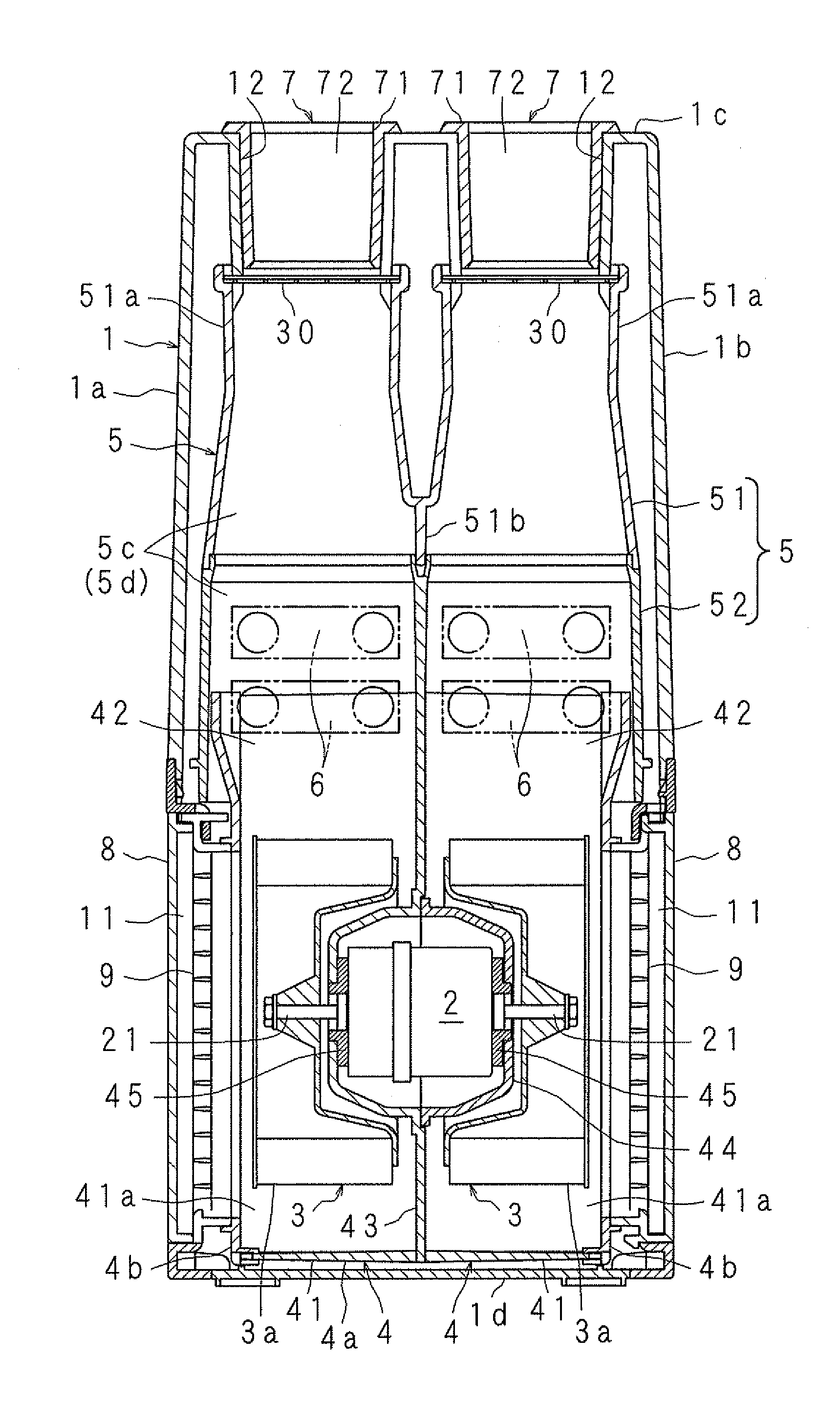
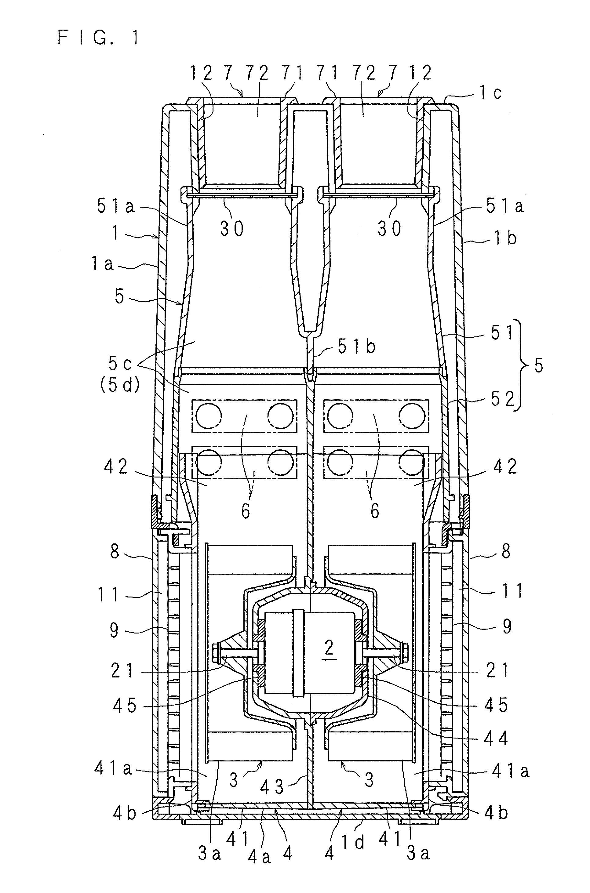
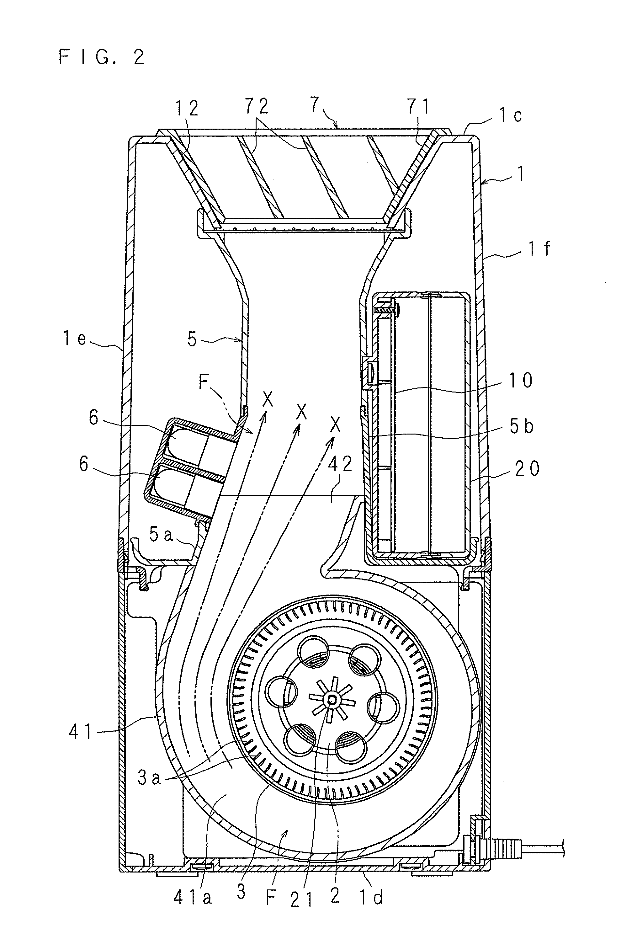
[0160]FIG. 1 is a vertical section front view illustrating the configuration of an ion generating apparatus according to the present invention. FIG. 2 is a vertical section side view illustrating the configuration of the ion generating apparatus. FIG. 3 is a front view illustrating the configuration of the ion generator, a part of which is not shown.

[0161]The ion generating apparatus illustrated in FIG. 1 includes: a housing 1 having suction ports 11, 11 at a lower portion of both side walls 1a, 1b separated and arranged in opposed position and having two engagement holes 12, 12 at a central portion of a top wall 1c; a motor 2 arranged at a lower portion in the housing 1 and having output shafts 21, 21 on both sides in the direction of the output shafts; two impellers 3, 3 mounted on the output shafts 21, 21 of the motor 2; two casings 4, 4 that house the impellers 3, 3 such that the impellers 3, 3 are rotatable; two ducts 5, 5 serving as tube sections that leads upward the airflow ...

embodiment 2

[0180]An embodiment in which the ion detecting apparatus according to the present invention is applied to an ion generating apparatus will be described below in detail. FIG. 4 is a vertical section front view illustrating the configuration of an ion generating apparatus according to the present invention, while FIG. 5 is a vertical section side view illustrating the configuration of an ion generating apparatus. FIG. 6 is a vertical section side view illustrating the configuration of the ion generator 6a. The other ion generators 6b, 6c and 6d have similar configuration as that of the ion generator 6a.

[0181]A housing is denoted by 1 in the drawings, the housing 1 including opposing both side walls 1a, 1b having suction ports 11, 11 at lower parts thereof and separated from each other, and a top wall 1c having two engagement holes 12, 12 at the central part thereof. A motor 2 having output shafts 21, 21 on both sides in the direction of rotation axis is provided at the lower part in ...

embodiment 3

[0240]The present invention will be described based on the drawings illustrating an embodiment thereof. FIG. 16 is a vertical section front view illustrating the configuration of an ion generating apparatus according to the present invention. FIG. 17 is a vertical section side view illustrating the configuration of an ion generating apparatus. FIG. 18 is a schematic front view illustrating a state where the ion generators 6a, 6b, 6c and 6d are attached on the front wall 5a.

[0241]A housing is denoted by the numeral 1 in the drawings, the housing 1 including both side walls 1a, 1b separated from and opposed to each other having suction ports 11, 11 at a lower part thereof, and a top wall 1c having two engagement holes (discharge ports) 12, 12 at the central portion thereof. At the lower portion in the housing 1, a motor 2 having output shafts 21, 21 on both sides of the direction of the rotating axis is arranged, two impellers 3, 3 housed in two casings 4, 4 to be freely rotatable be...


PUM


Abstract

An air blower including a motor 2 having output shafts 21, 21 on both sides in the axial direction and two impellers 3, 3 mounted on the respective output shafts 21, 21, and two ducts 5, 5 that individually allow passage of the air blown out by rotation of each of the impellers 3, 3 in the same direction and discharge the air to the outside are included. At a part or the whole of each of the ducts 5, 5, a laminar flow section that makes the flowing air laminar flow. An ion generating section is arranged at each laminar flow section so that ions generated by the ion generating section can effectively be included in the air, increasing the ion concentration of ions discharged in a room together with the air.

Description

TECHNICAL FIELD[0001]The present invention relates to an ion detecting apparatus that detects ions in the air and to an ion generating apparatus including the ion detecting apparatus.BACKGROUND ART[0002]In a residential room, bacteria, virus and the like such as serratia and bacillus are floating while unpleasant odors are attached to curtains, clothes and the like hung in the room. An air purifier is provided in such a room in order to clean the air in the room. The air purifier described in Patent Document 1 includes dielectrics that generate H+(H2O)n of a positive ion and O2−(H2O)n of a negative ion, and an air blower that discharges H+(H2O)n and O2−(H2O)n generated by the dielectrics in a room.[0003]The air purifier generates H+(H2O)n and O2−(H2O)n at the same time to produce hydrogen peroxide H2O2 or hydroxyl radical (.OH), which are active species, by chemical reaction. Since the hydrogen peroxide H2O2 or hydroxyl radical (.OH) shows extremely high activity, floating bacteria ...

Claims


Application Information

Patent Timeline
Patent Type & Authority Applications(United States)
IPC IPC(8): H01J27/02G01R29/00
CPCA61L9/22A61L2209/111B03C3/368B03C3/383H01T23/00B03C2201/24F24F2003/1635F24F2003/1682B03C3/68Y02A50/20F24F8/194F24F8/30F24F7/00
Inventor FUNABIKI, FUMIMASAITOH, TOMOHISAURAMOTO, YOSHIHIROHANAI, TAKAHIROTANOUE, YOSHIROHURUSHISAKI, MASATOKUMAGAI, YOSHIMI
Owner SHARP KK
Why Eureka
Try Eureka