Carbon Nanofiber-Metal Composite and Method for Preparing the Same
a carbon nanofiber and metal composite technology, applied in the direction of shielding materials, conductors, physical/chemical process catalysts, etc., can solve the problems of increasing the frequency of electromagnetization, affecting the efficiency of electromagnetization, etc., to achieve the effect of reducing the number of occurrences
Inactive Publication Date: 2011-06-30
CHEIL IND INC
View PDF10 Cites 15 Cited by
- Summary
- Abstract
- Description
- Claims
- Application Information
AI Technical Summary
Benefits of technology
[0013]The present invention provides a carbon nanofiber-metal composite that can have improved magnetic permeability and conductivity and thus can be useful as an electromagnetic shielding material.
[0014]The present invention further provides a method for making a carbon nanofiber-metal composite that can have improved magnetic permeability and conductivity which can be useful as an electromagnetic shielding material.
Problems solved by technology
Electromagnetic pollution is steadily increasing in daily life because the electromagnetic spectrum being used is moving to a higher frequency band, due to the increasing multifunctionality and miniaturization of electrical and electronic products and the development of information and communication equipment.
Because of this phenomenon, the electromagnetic spectrum radiated from certain sources may cause malfunctions and system errors in surrounding devices and may also damage the human body, such as inducing fever.
However, if a metal instrument has a complex pattern, processability can deteriorate and the weight of the metal instrument can increase.
Further, plating technologies can require complex processes, such as grease removal, etching, neutralizing, activating, accelerating, metalizing, activating, first plating, second plating, and third plating steps, which can impact productivity.
However, the metal layer is partially coated and the coating thickness of the metal layer is very thin.
Thus, the metal coated carbon nanotubes would not be expected to exhibit sufficient surface reflection caused by conductivity and / or absorption effect caused by magnetic permeability of the metal.
However, these methods have a disadvantage in terms of production cost, because the processes require high temperature heat treatment to remove the fibers to reduce weight.
In addition, the high temperature heat treatment process can melt the plated metal and destroy the manufactured fiber structure.
Method used
View moreImage
Smart ImageViewing Examples
Examples
examples
[0059]Carbon structures used in the Examples and Comparative Examples are as follows:
(A) Example
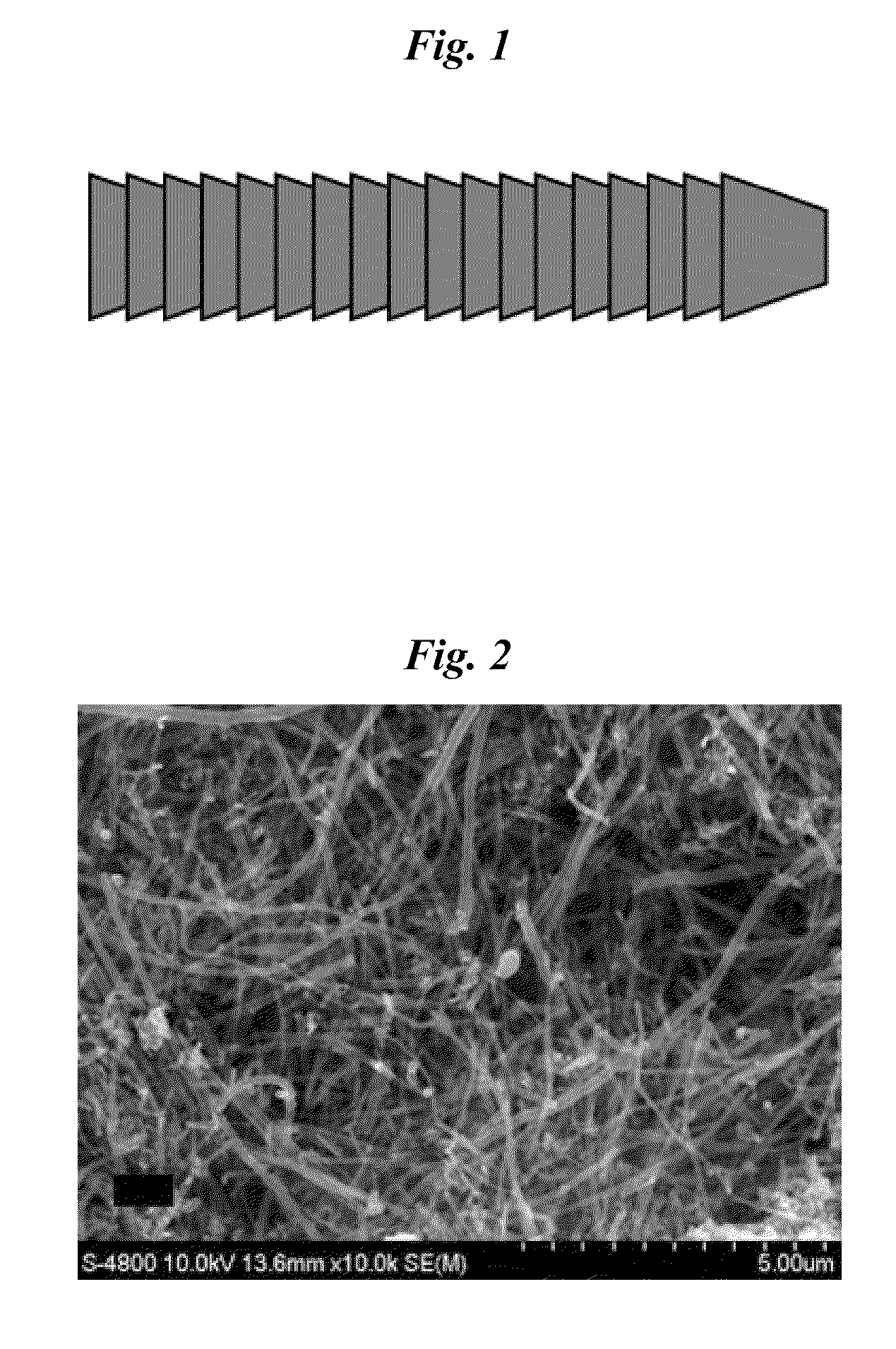
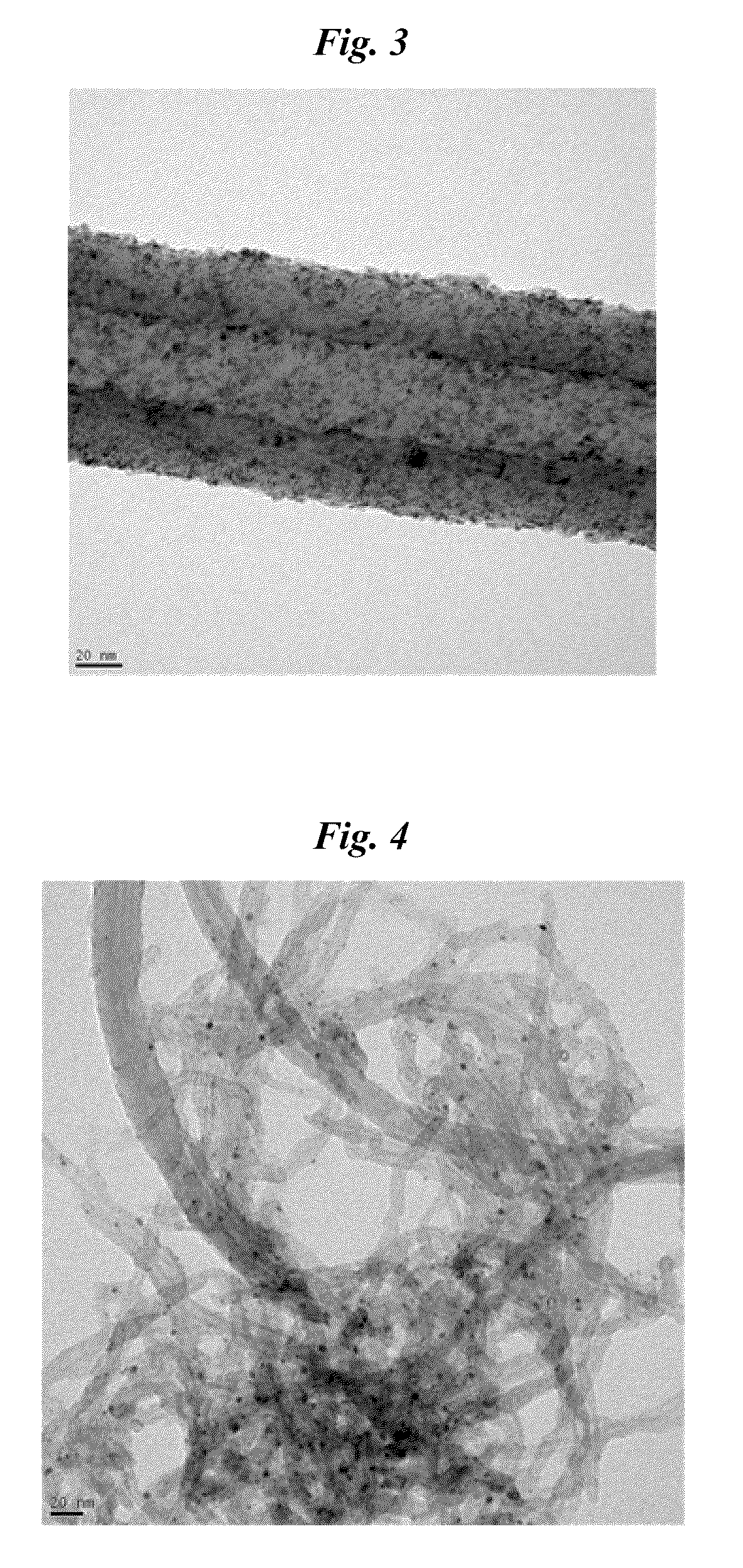
[0060]A carbon nanofiber including a plurality of laminated truncated, conic graphenes, a diameter of 200 nm and a length of 5 μm is used.
[0061]FIG. 2 is a scanning electron microscope image of the carbon nanofiber used in the examples.
Login to View More PUM
| Property | Measurement | Unit |
|---|---|---|
| aspect ratio | aaaaa | aaaaa |
| surface area | aaaaa | aaaaa |
| diameter | aaaaa | aaaaa |
Abstract
The present invention provides a carbon nanofiber-metal composite, which is formed by continuously coating a carbon nanofiber including a plurality of laminated truncated, conic graphenes with a metal. The carbon nanofiber-metal composite according to the present invention can have improved magnetic permeability and conductivity, and thus can be useful as an electromagnetic shielding material.
Description
CROSS-REFERENCE TO RELATED APPLICATIONS[0001]This application claims priority from Korea Patent Application No. 2009-0133885, filed Dec. 30, 2009, in the Korean Intellectual Property Office, the disclosure of which is incorporated herein by reference in its entirety.FIELD OF THE INVENTION[0002]The present invention relates to a carbon nanofiber-metal composite and method for preparing the same.BACKGROUND OF THE INVENTION[0003]Electromagnetic pollution is steadily increasing in daily life because the electromagnetic spectrum being used is moving to a higher frequency band, due to the increasing multifunctionality and miniaturization of electrical and electronic products and the development of information and communication equipment. Because of this phenomenon, the electromagnetic spectrum radiated from certain sources may cause malfunctions and system errors in surrounding devices and may also damage the human body, such as inducing fever. Therefore, there is increasing demand for el...
Claims
Login to View More Application Information
Patent Timeline
 Patent Type & Authority Applications(United States)
IPC IPC(8): H01B1/04B01J35/02B82Y30/00
CPCD06M11/83H05K9/009D06M2101/40B82B1/00C25D5/54
Inventor YOUM, KYOUNG TAELEE, YOUNG SIL
Owner CHEIL IND INC
Features
- R&D
- Intellectual Property
- Life Sciences
- Materials
- Tech Scout
- Unparalleled Data Quality
- Higher Quality Content
- 60% Fewer Hallucinations
Learn More Browse by: Latest US Patents, China's latest patents, Technical Efficacy Thesaurus, Application Domain, Technology Topic, Popular Technical Reports.
© 2025 PatSnap. All rights reserved.Legal|Privacy policy|Modern Slavery Act Transparency Statement|Sitemap|About US| Contact US: help@patsnap.com


