Salt water desalination using energy from gasification process

a technology of gasification process and desalination of salt water, which is applied in separation processes, vacuum distillation separation, vessel construction, etc., can solve problems such as energy inefficiency

Inactive Publication Date: 2011-07-07
GENERAL ELECTRIC CO
View PDF7 Cites 36 Cited by
  • Summary
  • Abstract
  • Description
  • Claims
  • Application Information

AI Technical Summary

Benefits of technology

The invention also enjoys the advantage of providing an improvement of the overall thermal efficiency in generating fresh no-salt potable water from salt water desalination processes, utilizing reaction heat from a partial combustion process. The invention can directly use raw syngas or generate process steam with raw syngas as a means to deliver heat to a desalination process, and eliminates equipment associated with process steam extractions for desalination, such as conventional main steam boilers, main steam turbo machinery and / or other main steam cycle process equipment, thereby further reducing costs.

Problems solved by technology

Energy inefficiencies arise when employing low pressure steam for driving a desalination plant.

Method used


Image

  • Salt water desalination using energy from gasification process
  • Salt water desalination using energy from gasification process
  • Salt water desalination using energy from gasification process

Examples


first embodiment

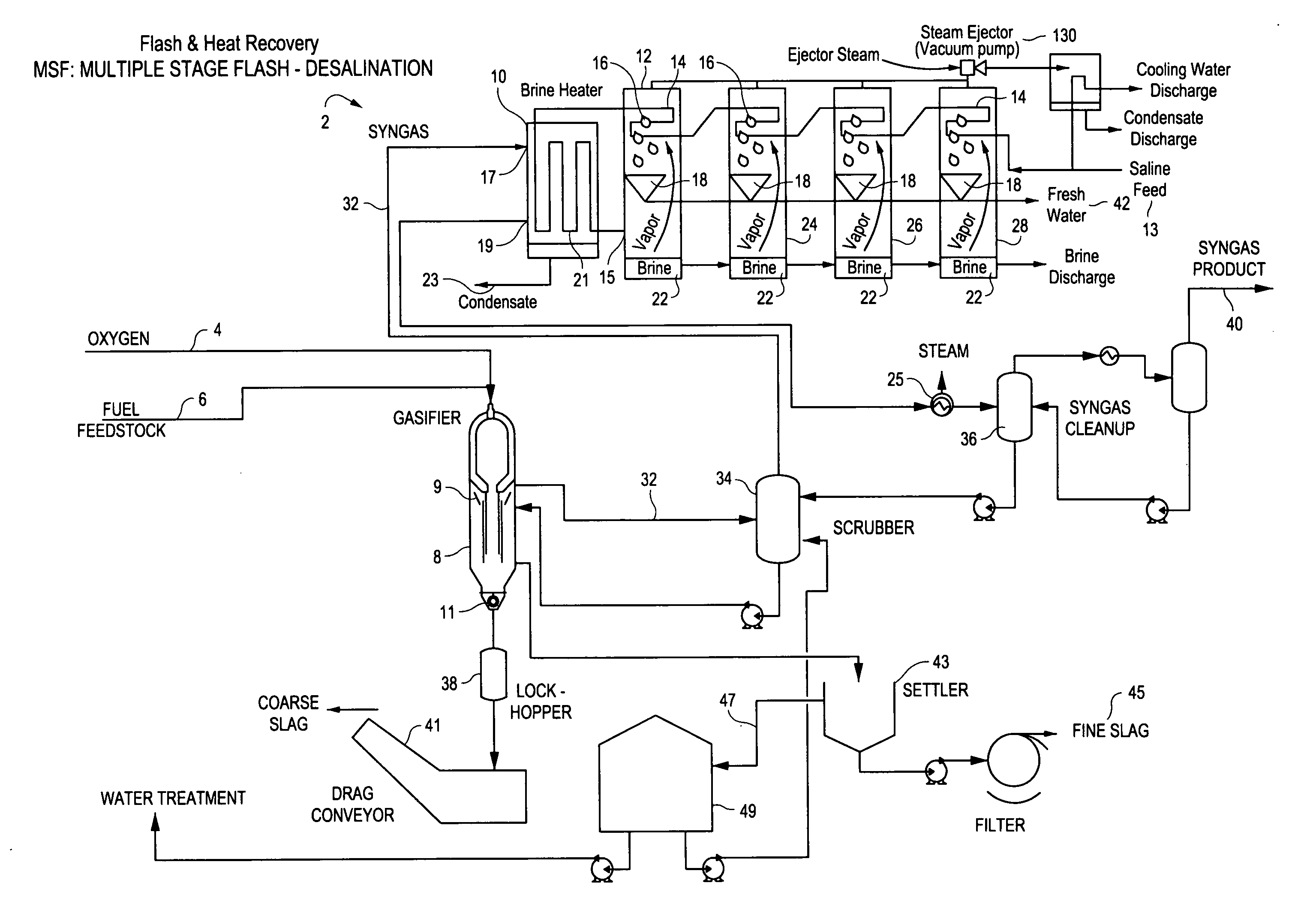
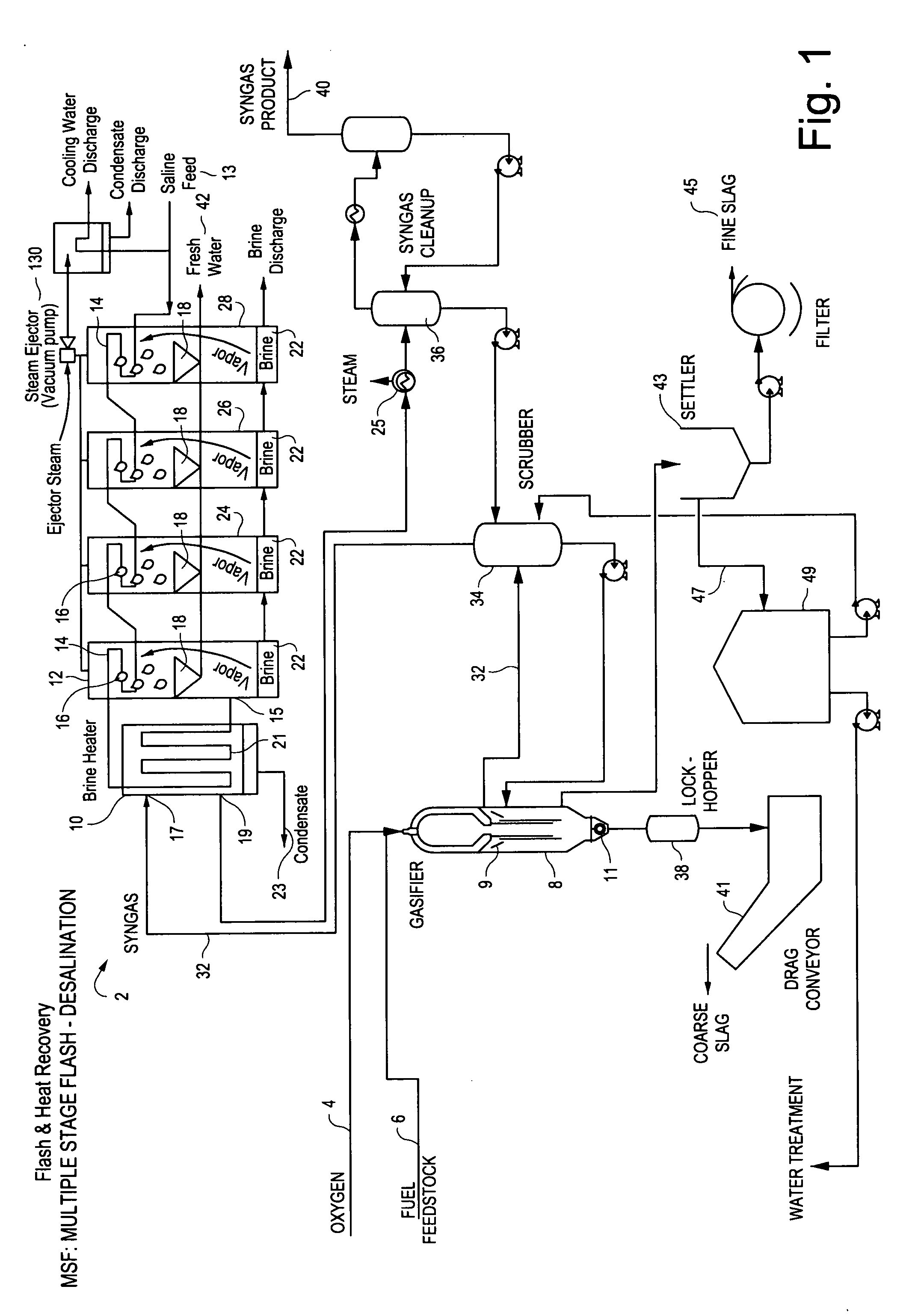
Referring to the drawings, FIG. 1 shows the process of the invention utilizing a multiple stage flash desalination system 2. In this process, an oxidant (for example oxygen) 4 and a fuel feedstock 6 are injected into gasifier 8 which serves as a source of synthetic gas (syngas). The rate of oxidant injection is controlled such that the amount of oxidant in the gasifier 8 is intentionally deprived resulting in an incomplete combustion process. Only a portion of the chemical energy contained in the fuel feedstock is converted into heat energy, while the unconverted chemical energy transforms into a raw synthetic gaseous energy source.

The produced synthetic gas exiting the gasifier 8 commonly contains ash and other elements that must be removed by downstream process equipment. The gasifier 8 shown in FIG. 1 also includes a water quench 9 for initial gas cooling with a funnel-shaped slag collector 11 at the bottom. The slag collector 11 acts as both a collector and chute, in that it col...

second embodiment

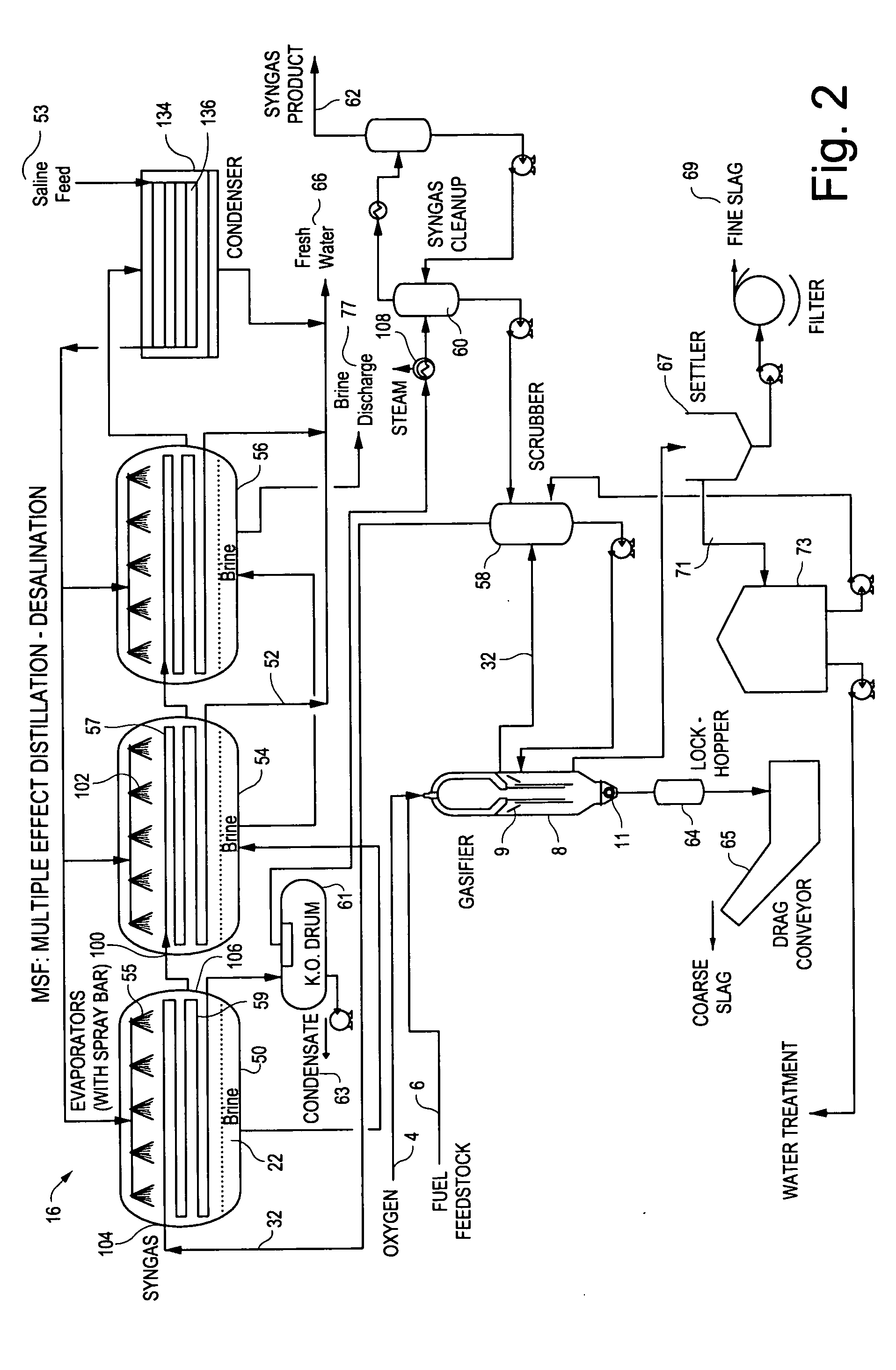
FIG. 2 illustrates the process of the invention utilizing a multiple effect distillation desalination system 16, where like numerals designate like components. In this process, an oxidant (for example oxygen) 4 and a fuel feedstock 6 are injected into a gasifier 8, which produces a hot raw synthetic gas (syngas) 32 which is quenched with syngas scrubber discharge water, resulting in a wet raw syngas cooled to a temperature acceptable for entry into syngas pathway 59 within evaporator 50 though syngas inlet port 104.

Prior to entry into the evaporator 50, the raw wet syngas 32 is passed through the scrubber 58 to be scrubbed of impurities during which the syngas is cooled. Further cooling occurs within the pathway 59, which is typically a metallic heat transfer coil, as a result of heat transfer with saline from saline source 53 brought into contact with the exterior of the coil 59, typically by spraying salt water through spray bar 55. Cooled syngas passes from the coil 59 through sy...


PUM

PropertyMeasurementUnit
wt %aaaaaaaaaa
wt %aaaaaaaaaa
temperatureaaaaaaaaaa

Abstract

System and process for producing no-salt water by desalination of salt water, by heating salt water directly with heated synthetic gas produced in a gasification reaction or by using steam produced using heated synthetic gas, to evaporate the salt water and produce no-salt water.

Description

The present invention relates to salt water desalination using multi-stage flash or multi-effect distillation in conjunction with a gasification process which produces syngas at elevated temperature and which is utilized to generate a fresh water supply.BACKGROUND OF THE INVENTIONSalt water desalination using multi-stage flash (MSF) or multi-effect distillation (MED) is a process that receives heat from a low pressure, high quality steam energy source. In this process, low pressure steam is generated with common boiler technology (see U.S. Pat. Nos. 4,338,199 and 5,441,548).It is known to use other forms of energy for desalination. For example, U.S. Pat. No. 5,421,962 utilizes solar energy for desalination processes.Energy inefficiencies arise when employing low pressure steam for driving a desalination plant. A need exists, therefore, to provide an improved process for carrying out a desalination process with improved energy efficiency. The present invention seeks to fill that need...

Claims


Application Information

Patent Timeline
Patent Type & Authority Applications(United States)
IPC IPC(8): C02F1/06C02F1/04B01D5/00
CPCB01D1/16B01D3/065B01D5/006C02F1/06C02F1/16Y02E20/16C10J3/86C10K1/08C10J2300/0959C10J2300/16C10J2300/169C10J3/466Y02A20/124Y02E20/18Y02W10/37
Inventor CONCHIERI, JOHN A.FAIR, DELOME D.
Owner GENERAL ELECTRIC CO
Why Eureka
Try Eureka