
System and method for sequestering emissions from engines

a technology of emission control system and emission storage method, which is applied in the direction of machines/engines, separation processes, lighting and heating apparatus, etc., can solve the problems of large volume of tanks, large energy requirements, and difficulty in separating nitrogen gas from carbon dioxide gas

Inactive Publication Date: 2011-07-14
PURIFY SOLUTIONS INC
View PDF0 Cites 13 Cited by
  • Summary
  • Abstract
  • Description
  • Claims
  • Application Information

AI Technical Summary

Benefits of technology

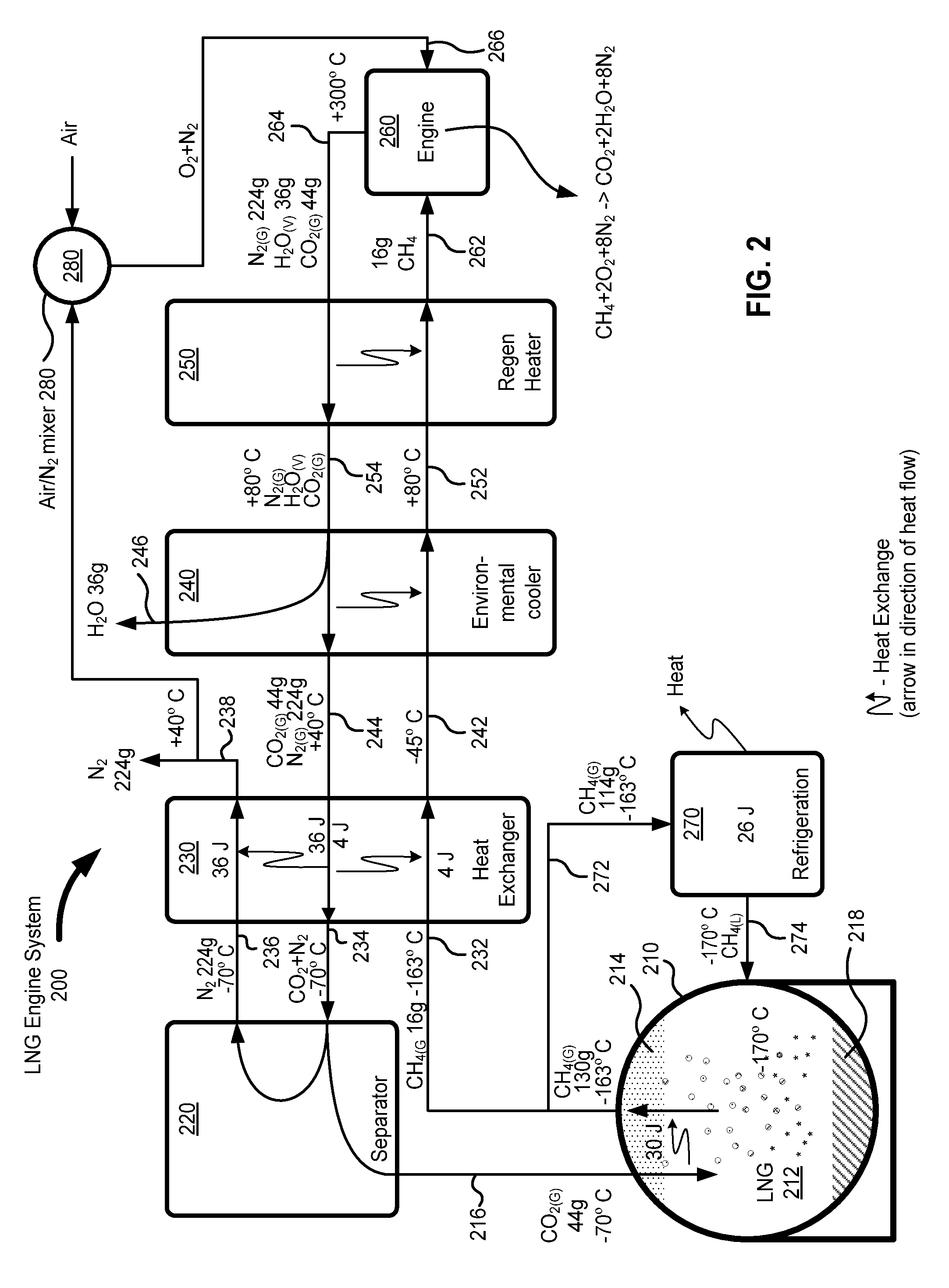
[0007]In an embodiment of the presently claimed invention, a liquefied natural gas (LNG) tank provides natural gas for burning in an engine. Exhaust emitted from the engine includes nitrogen gas, water vapor, and carbon dioxide. The exhaust gas may be cooled using heat exchange techniques, for example, reverse flow heat exchangers. Water may be separated from the exhaust gas using condensation techniques. Carbon dioxide may be separated from the remaining nitrogen. For example, a heat exchanger in combination with

Problems solved by technology

Unfortunately, a problem with returning nitrogen to the atmosphere without the carbon dioxide is that it is difficult to separate nitrogen gas from carbon dioxide gas and typically requires large amounts of energy.
There is also a problem with storing carbon dioxide gas, in that tanks having large volumes are required for handling, transportation, and storage.
As a ship consumes fuel during a voyage, the weight and balance changes to a point that the ship may become unstable.
Unfortunately, some fuel was inevitably discharged along with the seawater ballast.
This pollution has become an unacceptable form of pollution.
Unfortunately, the ballast tanks require a substantial volume within the ship that could otherwise be used for cargo.
Moreover, the requirement of separate ballast and fuel tanks inevitably results in a shift in the weight and balance for the ship as fuel is consumed in a fuel tank at a first position on the ship while a ballast tank is filled with seawater at a second position on the ship.
This increases the difficulty in designing a fuel / ballast system for achieving optimal weight and balance in all axes for various configurations of fuel consumption.

Method used


Image

  • System and method for sequestering emissions from engines
  • System and method for sequestering emissions from engines
  • System and method for sequestering emissions from engines

Examples


Embodiment Construction

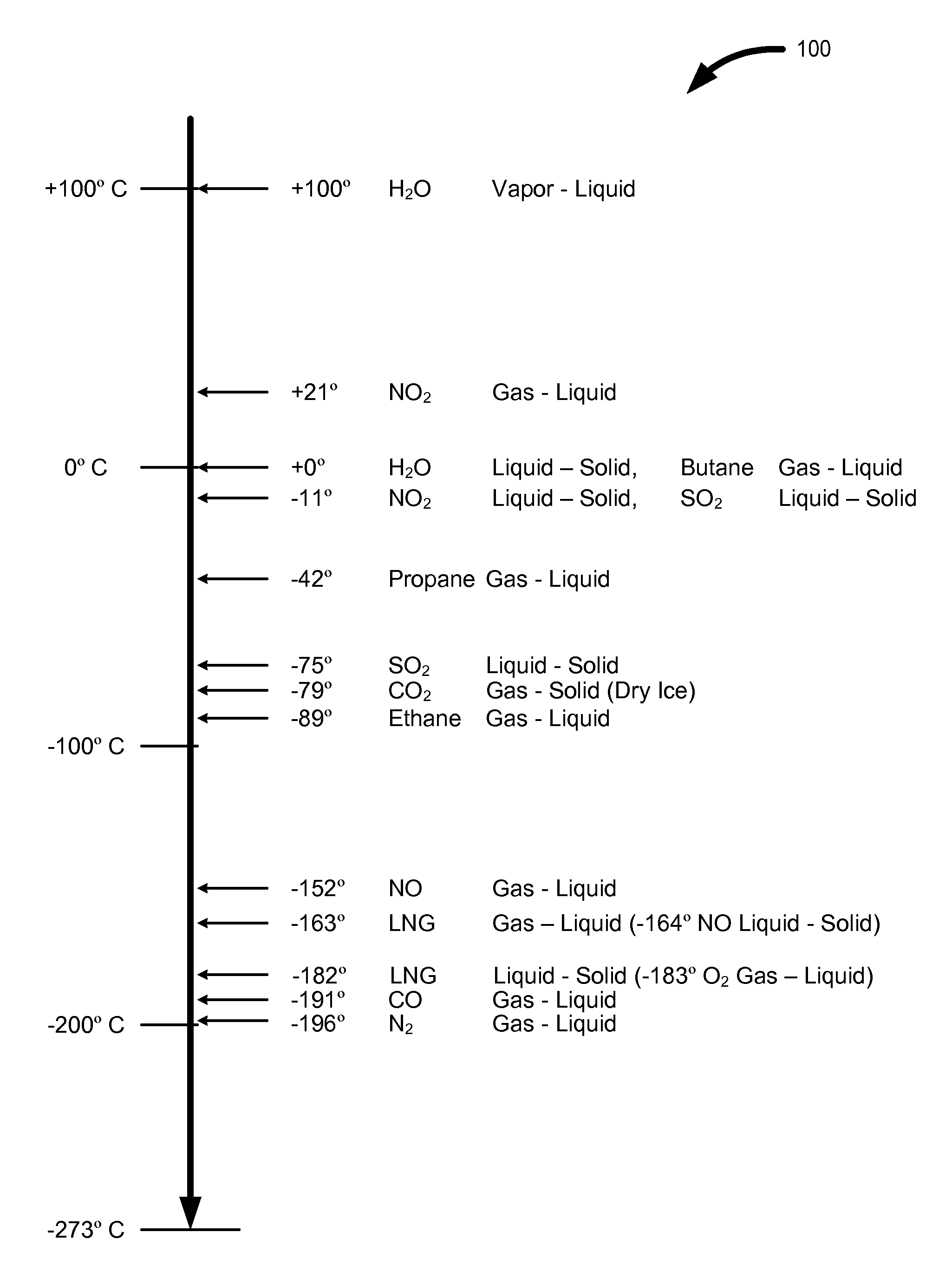
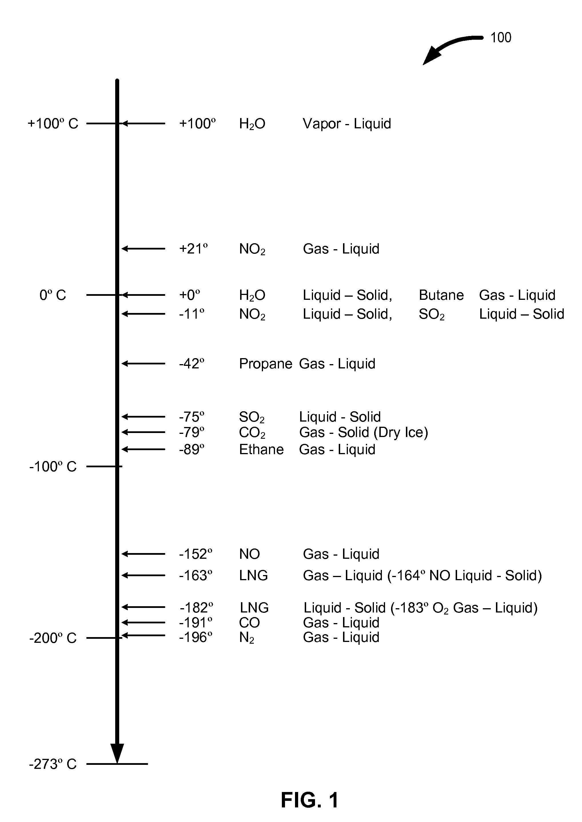
[0020]FIG. 1 is a chart 100 illustrating temperatures for phase changes of various molecules. The temperatures illustrated in FIG. 1 are approximate temperatures in degrees Celsius for phase changes that occur at about one atmosphere pressure. The illustrated phase changes include vapor to liquid for water (100°), gas to liquid for LNG (−163°), liquid to solid for LNG (−182°), and gas to solid (sublimation) for carbon dioxide to dry ice (−79°). The chart 100 further illustrates phase changes including gas to liquid for nitrogen dioxide (+21°), butane (0°), propane (−42°), ethane (−89°), nitric oxide (−152°), oxygen (−183°), carbon monoxide (−192°), and nitrogen (−196°). Additional phase changes illustrated in the chart 100 include liquid to solid for water (0°), nitrogen dioxide (−11°), and nitrous oxide (−164°). Natural gas includes primarily methane. However, natural gas includes ethane, propane, butane and other hydrocarbons. Since natural gas is primarily methane, the terms natu...


PUM


Abstract

A system is provided for sequestering carbon dioxide emitted in exhaust gas from an engine. The exhaust gas may be cooled using heat exchange techniques, for example reverse flow heat exchangers. Carbon dioxide may be separated from the exhaust gases, for example using fractional distillation, heat exchangers, and turbo chargers. The separated carbon dioxide may be stored, for example using injection deep into the earth for enhancing natural gas and oil extraction. Alternatively, the separated carbon dioxide may be cooled to solid carbon dioxide and stored, for example, in an LNG tank for use as ballast onboard a ship or for use in industry.

Description

CROSS-REFERENCE TO RELATED APPLICATIONS[0001]The present application claims the priority and benefit of U.S. patent application No. 61 / 293,609 titled “Zero-Emissions Engines,” filed Jan. 8, 2010. The disclosures of the above U.S. patent application is incorporated by reference herein in its entirety.BACKGROUND[0002]1. Field of the Invention[0003]The present disclosure generally relates to emission control systems. The present disclosure more specifically relates to sequestering emissions from an engine during operation.[0004]2. Description of Related Art[0005]The major components of engine exhaust are nitrogen, water vapor, and carbon dioxide. For example, 100 grams (g) of exhaust gas may include approximately 73 g of nitrogen gas, 12 g of water vapor, 14 g of carbon gas dioxide, and 1 g of trace pollutants. Water vapor can be condensed from exhaust gas according to standard techniques and safely returned to the environment. Trace pollutants can be removed using emissions control sy...

Claims


Application Information

Patent Timeline
IPC IPC(8): F01N3/02F25B7/00
CPCB01D53/002B01D53/922B01D2257/504B01D2258/018Y02T10/20F01N5/02F01N5/04Y02T10/16F01N3/0205Y02T10/12
Inventor EVANS-BEAUCHAMP, LINCOLN
Owner PURIFY SOLUTIONS INC
Learn More