Methods for treating superalloy articles, and related repair processes

a superalloy and repair process technology, applied in the field of metal and metal alloys, can solve the problems of turbine engine blade cracks, cracks primarily occurring, and components of gas turbine engines to develop cracks

Active Publication Date: 2011-07-14
GENERAL ELECTRIC CO
View PDF17 Cites 46 Cited by
  • Summary
  • Abstract
  • Description
  • Claims
  • Application Information

AI Technical Summary

Problems solved by technology

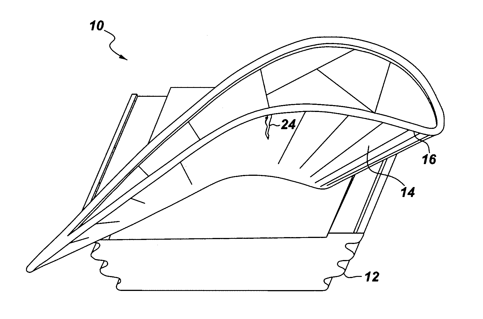
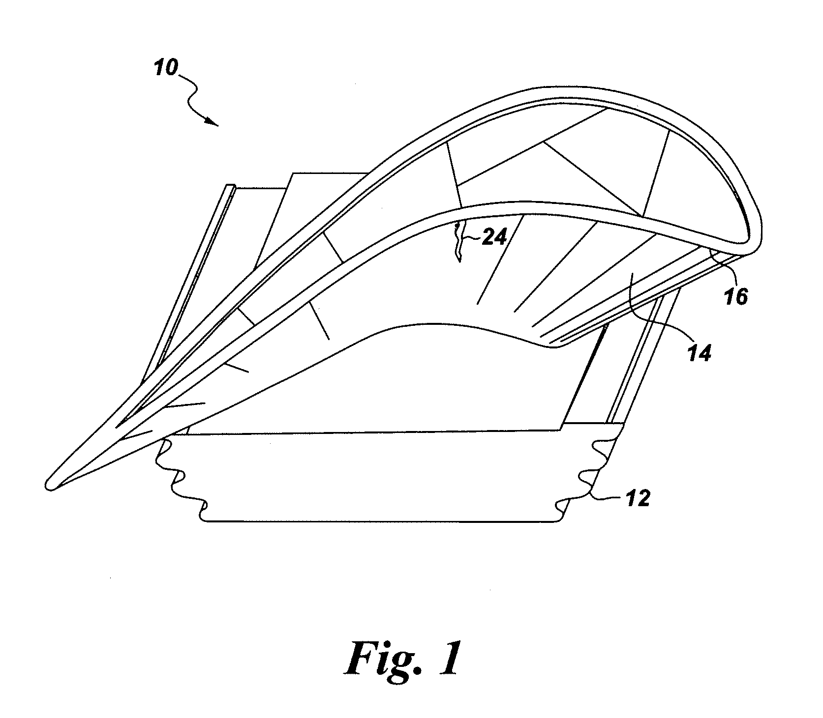
It is common for gas turbine engine components to develop cracks, over the course of their operation.
These cracks primarily arise over time, from extreme temperatures and pressures experienced by the turbine engines.
Of particular concern are cracks which form in turbine engine blades, e.g., the high pressure turbine (HPT) blades closest to the engine combustor.
For most of these techniques, the initial preparation of the repair surface is critical.
The undesirable presence of chemically-stable oxides, as well as any metallic bond-coat or ceramic thermal barrier coating material, can greatly impede welding or brazing of a repair surface.
While the grinding techniques are useful in many situations, they are also time-consuming.
Furthermore, in the case of cracks within turbine airfoil surfaces, grinding procedures are often limited to a crack depth of about 0.35 inch (8.9 mm).
Thus, deep cracks in components like HPT blades cannot always be successfully “prepped” for repair; and attempts to carry out the preparation process can sometimes result in “weld drop”.
While fluoride ion cleaning and etching processes are effective in some situations, they also may exhibit significant disadvantages.
As an example, these techniques can require relatively long process times if the workpiece surface is to be completely cleaned.
These materials are corrosive and toxic, and require special handling and disposal procedures.
Furthermore, the FIC process can attack the materials which form protective coatings on superalloy articles, e.g., nickel-aluminide or platinum-aluminide materials.

Method used


Image

  • Methods for treating superalloy articles, and related repair processes
  • Methods for treating superalloy articles, and related repair processes
  • Methods for treating superalloy articles, and related repair processes

Examples


Embodiment Construction

[0017]The various compositional and process ranges disclosed herein are inclusive and combinable (e.g., ranges of “up to about 25 wt %”, or, more specifically, “about 5 wt % to about 20 wt %”, are inclusive of the endpoints and all intermediate values of the ranges). Moreover, the term “combination” is inclusive of blends, mixtures, alloys, reaction products, and the like. Furthermore, the terms “first,”“second,” and the like, herein do not denote any order, quantity, or importance, but rather are used to distinguish one element from another. The terms “a” and “an” herein do not denote a limitation of quantity, but rather denote the presence of at least one of the referenced items. The modifier “about” used in connection with a quantity is inclusive of the stated value, and has the meaning dictated by context, (e.g., includes the degree of error associated with measurement of the particular quantity). The suffix “(s)” as used herein is intended to include both the singular and the p...


PUM

PropertyMeasurementUnit
depthaaaaaaaaaa
depthaaaaaaaaaa
widthaaaaaaaaaa

Abstract

A method is described, for treating a superalloy substrate which includes at least one cavity containing adherent metal oxide material on its surface. A short-pulsed, high repetition rate laser beam is directed against the cavity surface for a period of time sufficient to remove substantially all of the adherent metal oxide material. The laser beam is characterized by a peak power density in the range of about 10 megawatts / cm2 to about 10 gigawatts / cm2. In another embodiment, a high-power, short-pulsed, high repetition rate laser beam is directed to a region on the substrate which includes the cavity, under laser operational conditions which are capable of cutting into the superalloy material; so that a boundary region is formed within the substrate, which encloses the cavity. The cavity can be a crack in a turbine blade, and the crack can be repaired after treatment, by welding, or by another suitable technique.

Description

BACKGROUND OF THE INVENTION[0001]This invention relates generally to metals and metal alloys used in high temperature applications. In some specific embodiments, it relates to methods for treating superalloy components to prepare them for additional repair processes.[0002]Superalloys are often the materials of choice for components intended for high-temperature environments. As an example, turbine blades and other parts of turbine engines (e.g., gas turbine engines) are often formed of nickel-based superalloys because they need to maintain their integrity at temperatures of at least about 1000° C.-1150° C. Protective coatings, often referred to as thermal barrier coatings or “TBC”s, effectively increase the operating temperature of turbine components by maintaining or reducing the surface temperature of the alloys used to form the various engine components.[0003]It is common for gas turbine engine components to develop cracks, over the course of their operation. In many cases, the c...

Claims


Application Information

Patent Timeline
Patent Type & Authority Applications(United States)
IPC IPC(8): B23K9/16B23K26/06B23K9/00B23K26/00
CPCF05D2230/90B23K2201/001F05D2230/13B23K26/36F01D5/005B23K2101/001B23K26/40
Inventor QI, HUANGUPTA, BHUPENDRA KUMARJONES, MARSHALL GORDON
Owner GENERAL ELECTRIC CO
Why Eureka
Try Eureka