Carbon fibrous aggregator, method for manufacturing thereof, and composite material including thereof

a carbon fiber and aggregator technology, applied in the field of aggregators, can solve the problems of insufficient control of cnt synthesis under nano level, poor manufacturing efficiency, and insufficient fulfillment of the need for ideal additives, and achieve uniform electrical conductivity and stably various physical properties

Inactive Publication Date: 2011-07-14
HODOGOYA CHEMICAL CO LTD
View PDF6 Cites 8 Cited by
  • Summary
  • Abstract
  • Description
  • Claims
  • Application Information

AI Technical Summary

Benefits of technology

[0054]According to the present invention, since individual carbon fibrous aggregator has plural granular parts, each of the granular parts being a base point for plural carbon fibers which are mutually independently extended outwardly from the base point and show a three dimensional expansion in all, and thus carbon fibers of 5-300 nm in outer diameter are bound together by their respective granular parts produced in a growth process of the carbon fibers so that the concerned plural carbon fibers extend outwardly from the granular part, the carbon fibrous aggregators can disperse promptly into a matrix such as a resin upon adding while maintaining their bulky structure. Even when they are added at a small amount to a matrix, they can be distributed uniformly over the matrix.
[0055]Further, since the outside diameters of the carbon fibers show a sharp distribution, the carbon fibrous aggregators can be utilized as an additive, particularly, additive for injection molding of resin, which is able to provide a dispersion of giving a uniform electrical conductivity throughout the surface and interior regions of the composite material, or as an additive which contribute stably various physical properties of the injection molded product. For instance, the aggregators are able to use for forming a composition material which exhibits a narrow range of variation in the electrical conductivity.

Problems solved by technology

However, such controls in the synthesis for CNTs of under nano levels have not been sufficiently attained yet.
Thus, they do not fulfill the need for ideal additives that is capable of improving various characteristics, such as electric conductivity, of a matrix effectively at low dosages.
With respect to the carbon fibrous agglomerates disclosed in the Patent Literature 2, it is necessary to provide an additional step for fixing carbon fibers at their mutual contacting points after synthesis of the carbon fibers, and thus the efficiency of manufacturing becomes worse.
Further, since the carbon fibrous agglomerate is manufactured by heating carbon fibers in a state such that mutual contacting points among the carbon fibers are formed by compression molding after synthesis of the carbon fibers, and wherein fixing of fibers at the contacting points is done by carbonization of organic residues primarily attached to the surface of the carbon fibers, or carbonization of an organic compound additionally added as a binder, the affixing forces at the contacting points are weak.
In addition, the electrical properties of the carbon fibrous agglomerate per se are not well, although a certain degree of improvement in the electrical properties would be expected as compared with the case of pulverized monofibrous carbon fibers.
Thus, when these carbon fibrous agglomerates are added to a matrix such as a resin, the carbon fibers fixed at the contacting points are easily detached from each other, and the carbon fibrous agglomerates are no longer maintained in the matrix.
Therefore, it is difficult to construct preferable conductive paths in a matrix such that good electrical properties may be conferred on the matrix by a small additive amount of the fibrous agglomerates.
Furthermore, when a binder is added to promote fixing and carbonization at the contacting points, fibers in the obtained fibrous agglomerates would have large diameters and inferior surface characteristics because the added binder is attached to the whole surface area of the fibers rather than to a limited area on the contacting points.
However, since a raw material supplying part used in the vapor phase method adapts a way of activating the reaction by injecting the catalyst which is utilized in the early stage of carbon fiber synthesis toward the inner wall of the reaction chamber, and thus the catalyst is produced by coming into collision with the inner wall of the reaction chamber, it is considered that the turbulence of flows at the region of the catalyst production and the neighborhood of the region is very large.
Thus, it is difficult to produce carbon fibers having a more sharp distribution of the diameter.
In addition, since the method where the catalyst comes into collision with the inner wall of the reaction chamber uses only a part of the surface area of the inner surface of the reaction chamber, and it does not use the internal space of the reaction chamber, it will not be suitable to a more developed mass production of carbon fibers.
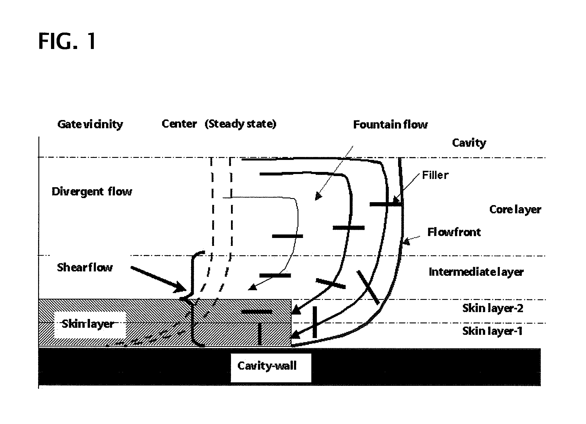
Thus, when the carbon fibrous structures are added to a resin in order to give the electrical conductivity, or when a composite product is manufactured by the injection molding process, a fear that the skin layer of the product becomes thicker will arise as described below, and the variation in the data of electrical conductivity for the products will be large.
However, in this process, since the reaction is activated by injecting the catalyst which is utilized in the early stage of carbon fiber synthesis toward the inner wall of the reaction chamber in order to produce the branched carbon fiber, and thus the same reasons as described above go for this process, it is expected that the production of carbon fibers having a more sharp distribution of the diameter is difficult.
However, since the method described in this literature depends on charring of the polymer, it is not suitable to the mass production.

Method used


Image

  • Carbon fibrous aggregator, method for manufacturing thereof, and composite  material including thereof
  • Carbon fibrous aggregator, method for manufacturing thereof, and composite  material including thereof
  • Carbon fibrous aggregator, method for manufacturing thereof, and composite  material including thereof

Examples


example 1

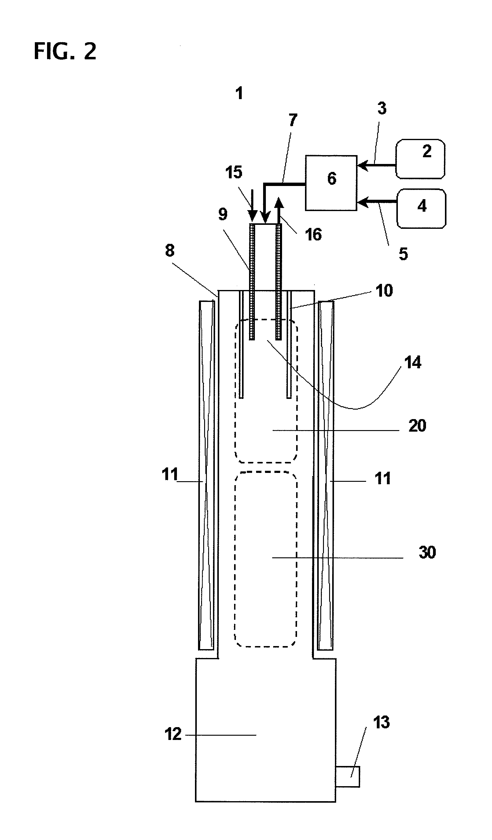
[0216]In Example 1, using raw material blending ratio, temperature conditions, and gas flow rates as shown in Table 7, and setting the operation condition to 3 hours, the first intermediate of the carbon fibrous aggregators was synthesized.

[0217]On the operation, the temperature control of the temperature zones (A), (B), and (C) shown in FIG. 5 was performed by setting the cooling gas flow rate to 8 NL / min. The reaction yield (=(weight of the obtained carbon fiber aggregators / weight of carbon in the raw material)×100) was found to be 41.1%. With respect to the carbon fibrous aggregators which were obtained from the first intermediate after undergoing the above mentioned steps such as the heat treatment, it was found that the mean outer diameter of fibers was 19.0 nm, the standard deviation of fiber outer diameters was 5.5 nm, the coefficient of variation of the fiber outer diameters was 28.9%. The distribution of the fiber diameters is shown in Table 1, and the distribution histogra...

example 2

[0218]In Example 2, using raw material blending ratio, temperature conditions, and gas flow rates as shown in Table 7, and setting the operation condition to 3 hours, the first intermediate of the carbon fibrous aggregators was synthesized.

[0219]On the operation, the temperature control of the temperature zones (A), (B), and (C) shown in FIG. 5 was performed by setting the cooling gas flow rate to 6 NL / min. The reaction yield was found to be 61.1%. With respect to the carbon fibrous aggregators which were obtained from the first intermediate after undergoing the above mentioned steps such as the heat treatment, it was found that the mean outer diameter of fibers was 37.8 nm, the standard deviation of fiber outer diameters was 9.9 nm, the coefficient of variation of the fiber outer diameters was 26.2%. The distribution of the fiber diameters is shown in Table 2, and the distribution histogram thereof is shown in FIG. 7.

example 3

[0220]In Example 3, using raw material blending ratio, temperature conditions, and gas flow rates as shown in Table 7, and setting the operation condition to 3 hours, the first intermediate of the carbon fibrous aggregators was synthesized.

[0221]On the operation, the temperature control of the temperature zones (A), (B), and (C) shown in FIG. 5 was performed by setting the cooling gas flow rate to 4 NL / min. The reaction yield was found to be 67.8%. With respect to the carbon fibrous aggregators which were obtained from the first intermediate after undergoing the above mentioned steps such as the heat treatment, it was found that the mean outer diameter of fibers was 61.5 nm, the standard deviation of fiber outer diameters was 14.3 nm, the coefficient of variation of the fiber outer diameters was 23.3%. The distribution of the fiber diameters is shown in Table 3, and the distribution histogram thereof is shown in FIG. 8.


PUM

PropertyMeasurementUnit
outer diameter distributionaaaaaaaaaa

Abstract

Disclosed is a carbon fibrous aggregator obtained by a chemical vapor phase growing method, which comprises plural granular parts, and plural carbon fibers which are mutually independently extended outwardly from their respective granular parts so that each granular part is associated with two or more of carbon fibers, wherein the carbon fibers show a three dimensional expansion in all; andwhich show a three dimensional network structure of the carbon fibers at least in a part by a state that at least a part of the plural carbon fibers extended from one granular part is linked with another granular part;wherein mean length of carbon fibers which link two granular parts together is of 3.0-20.0 μm, andwherein a coefficient of variation, CV, ((standard deviation / mean value)×100) which is obtained on a determination of outer diameter distribution of the carbon fibers which constitute the aggregator of carbon fiber is not more than 30%.

Description

[0001]The present application is a continuation-in-part of International Application No. PCT / JP2009 / 062889, filed on Jul. 16, 2009, and claims the benefit of priority from Japanese Patent Application No. 2008-185270, filed on Jul. 16, 2008, the contents of which are herein incorporated by reference in their entireties.TECHNICAL FIELD[0002]This invention relates to an aggregator of carbon fibers in which outside diameters of the carbon fibers show a sharp distribution, a method for manufacturing thereof, and a composite material including the aggregators. More particularly, this invention relates to the aggregator of carbon fibers, wherein plural numbers of carbon fibers are independently elongated from granular part(s), and which shows a three dimensional expansion in all, and thus a plural number of the aggregators are able to be utilized as additives to be added to a material such as resin, ceramics, metal, etc., to improve a physical property of the material, such as electric, me...

Claims


Application Information

Patent Timeline
Patent Type & Authority Applications(United States)
IPC IPC(8): C09K5/00
CPCB82Y30/00B82Y40/00C01B31/0226C01P2002/82C08J5/042C08J5/047Y10T428/30C22C49/14D01F9/127Y10T428/2982Y10T428/2927Y10T428/298C08J5/10C01B32/16Y10T428/249924
Inventor HITOE, YOSHINORISUZUKI, JUN
Owner HODOGOYA CHEMICAL CO LTD
Why Eureka
Try Eureka