Systems, methods, and apparatuses for detecting digital television (DTV) communications signals

a technology of digital television and communication signals, applied in the field of communication, can solve the problems of reducing the filter order or length required, and the statistical significance of the background noise level estimate is much higher, and achieves the effect of reducing error rates and improving detection sensitivity

Inactive Publication Date: 2011-07-14
SAMSUNG ELECTRO MECHANICS CO LTD
View PDF4 Cites 12 Cited by
  • Summary
  • Abstract
  • Description
  • Claims
  • Application Information

AI Technical Summary

Benefits of technology

[0012]Embodiments of the invention may support a method and system for detecting a DTV communications signal. Indeed, an embodiment of the invention may be able to detect weak signals, for example, those that are weaker than the background noise energy such as those with a signal-to-noise-ratio (SNR) of −20 dB or less. Furthermore, DTV signal sensing can be done in a short, prespecified time period ranging from a millisecond to over a second with longer sensing times providing better detection sensitivity and lower error rates. The false alarm rate (FAR) in accordance with an example embodiment of the invention may be invariant to the level of background noise, and thus may allow consistent FAR performance in a variety of environments without prior knowledge of the level of background noise. One or more of the foregoing can be accomplished with baseband (BB) digital signal processing after converting the received DTV signal from its communicated RF frequency down to a low-intermediate frequency (IF) or BB frequency, thereby enabling an economically viable low-cost solution.

Problems solved by technology

However, performing the filtering operation as a cascade of alternating LPF and decimation stages may significantly reduce the filter order or length required to achieve the same narrowband characteristics.
The use of this larger frequency band may result in much higher statistical significance of the background noise level estimate.

Method used


Image

  • Systems, methods, and apparatuses for detecting digital television (DTV) communications signals
  • Systems, methods, and apparatuses for detecting digital television (DTV) communications signals
  • Systems, methods, and apparatuses for detecting digital television (DTV) communications signals

Examples


Embodiment Construction

[0025]The present invention now will be described more fully hereinafter with reference to the accompanying drawings in which some, but not all, embodiments of the invention are shown. Indeed, these inventions may be embodied in many different forms and should not be construed as limited to the embodiments set forth herein; rather, these embodiments are provided so that this disclosure will satisfy applicable legal requirements. In other instances, well known methods, procedures, components, and representations are not described in detail because they would obscure the invention in unnecessary detail. Like numbers refer to like elements throughout.

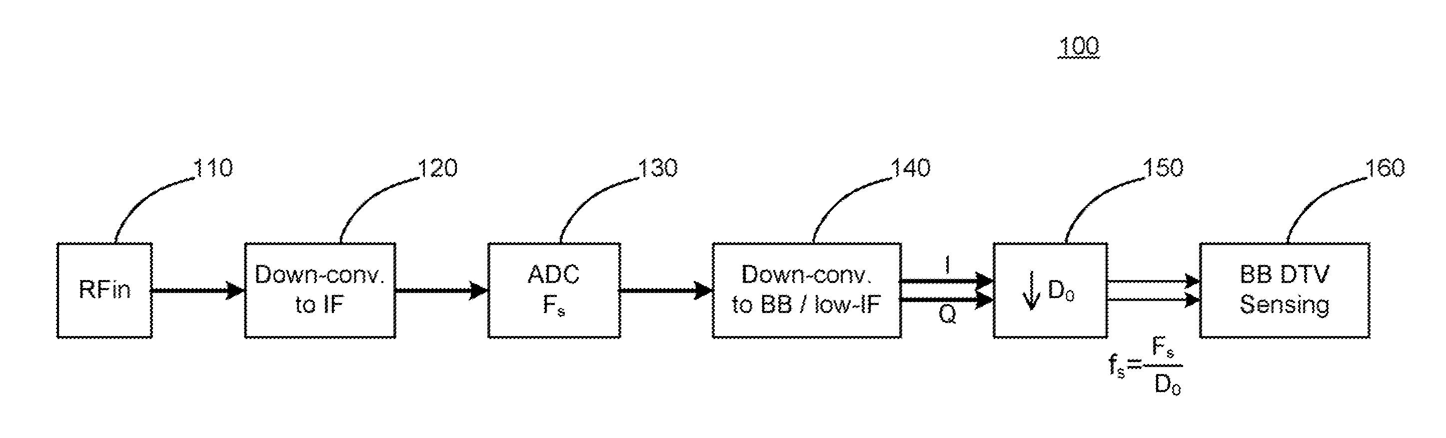
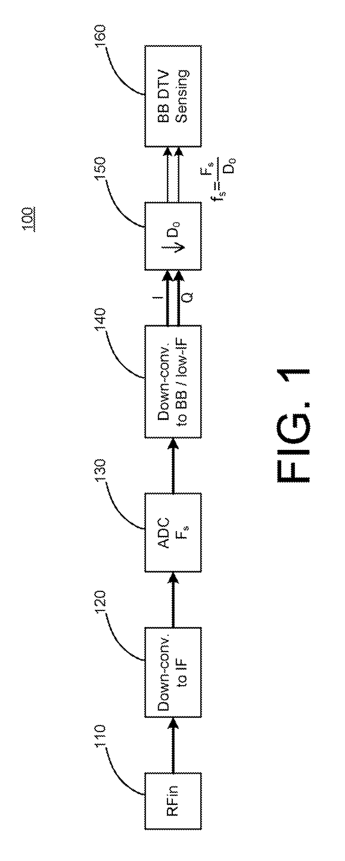
[0026]FIG. 1 illustrates an example of a system 100 supporting digital television (DTV) signal detection, according to an example embodiment of the invention. In general, the system 100 may be configured to convert a radio frequency (RF) airwave signal, at a frequency which can contain an RF DTV signal, into a low intermediate-frequency (I...


PUM


Abstract

Embodiments of the invention may provide systems and methods for detecting the presence a DTV signal such as an ATSC DTV signal. The system and methods may be applied to a received RF signal that has been down-converted to a baseband or low-IF digitized signal. The systems and methods may detect a presence of a DTV signal by searching for its characteristic pilot signal, known to reside in a fixed frequency range for all valid DTV signals. This pilot signal may be extracted by processing the baseband or low-IF signal in multiple stages. The first stage may reduce the signal information to that pertaining to the frequency band covering all valid pilot frequencies and commensurately reduces the sampling rate, and hence computational complexity of subsequent operations. A second stage may then efficiently operate on this reduced rate signal to focus on a series of particular pilot frequencies for interrogation. For each such candidate frequency, the cyclostationarity of the signal may be measured and tested for statistical significance relative to the background energy to yield an effective test that is invariant with respect to the background noise level. In a simplified case, this can correspond to measuring the energy in a very tight candidate subband normalized against the energy from a larger subband. Furthermore, the energy in the candidate subband can be taken as the energy in a Fourier series coefficient.

Description

RELATED APPLICATION[0001]The present application is a non-provisional application claiming priority to U.S. Provisional Application No. 61 / 293,321, filed on Jan. 8, 2010, and entitled “SYSTEMS, METHODS, and APPARATUSES FOR DETECTING DTV COMMUNICATIONS SIGNALS,” which is hereby incorporated by reference in its entirety as if fully set forth herein.FIELD OF THE INVENTION[0002]Embodiments of the invention relate generally to the field of communications and more specifically to the detection of digital television (DTV) signals in cognitive radio systems.BACKGROUND OF THE INVENTION[0003]The premise of a cognitive radio (CR) is to increase the utilization of airwave spectra for radio frequency (RF) communications by using locally unoccupied channels or frequency bands for unlicensed wireless communications. The specific details governing operation of CR have been defined by standards bodies such as the IEEE 802.22 group and CogNeA alliance.[0004]Central to the operation of CR communicatio...

Claims


Application Information

Patent Timeline
Patent Type & Authority Applications(United States)
IPC IPC(8): H04N17/00
CPCH04N17/004
Inventor KIM, ANDREW JOOOH, SEUNGMOKKUHN, MATTHEWNAYAR, BOBHUR, YOUNGSIK
Owner SAMSUNG ELECTRO MECHANICS CO LTD
Why Eureka
Try Eureka