Forming simulation method, forming simulator, program and recording medium therefor, and simulation-based forming method

a technology of simulation and forming, applied in the field of simulation-based forming method, forming simulation method, forming simulator, program and recording medium therefor, can solve the problems of uneven distortion, difficult to specify springback-inducing areas, and parts precision may decrease, etc., to achieve accurate forming, accurate forming, and accurate forming

Active Publication Date: 2011-07-14
NIPPON STEEL CORP
View PDF5 Cites 13 Cited by
  • Summary
  • Abstract
  • Description
  • Claims
  • Application Information

AI Technical Summary

Benefits of technology

[0037]According to the aspects (1) and (2) of the present invention, springback-inducing areas during forming of the elastic-plastic material can be specified by a simple calculation instead of complicated and time-consuming calculation, such as a matrix operation of large-scale simultaneous equations. As a result, accurate forming can be provided.
[0038]According to the aspects (3) and (4) of the present invention, springback-inducing areas during forming of the elastic-plastic material are specified still more reliably than in the present inventions (1) and (2), and accurate forming can be provided.
[0039]According to the aspects (5) and (6) of the present invention, springback-inducing areas during forming of the elastic-plastic material are specified still more reliably than in the aspects (3) and (4), and accurate forming can be provided.
[0040]According to aspects (7) to (10) of the present invention, on the basis of the results of the simulation methods recited in (1) to (6), even if the product to be processed has a complicated configuration, springback-inducing areas during press-forming can be efficiently specified as a pinpoint manner and springback induced in the areas are controlled so that a forming method of an elastic-plastic material excellent in dimensional accuracy can be provided.

Problems solved by technology

When such springback (i.e., elastic recovery) is large in amount, part precision may decrease.
Since press-formed products usually have complicated configurations, they are not uniformly distorted during forming.
It is therefore not easy to specify springback-inducing areas.

Method used


Image

  • Forming simulation method, forming simulator, program and recording medium therefor, and simulation-based forming method
  • Forming simulation method, forming simulator, program and recording medium therefor, and simulation-based forming method
  • Forming simulation method, forming simulator, program and recording medium therefor, and simulation-based forming method

Examples


first embodiment

[0077]Referring now to FIGS. 1 to 8, the present invention will be described in detail.

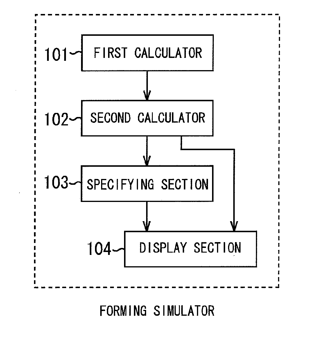
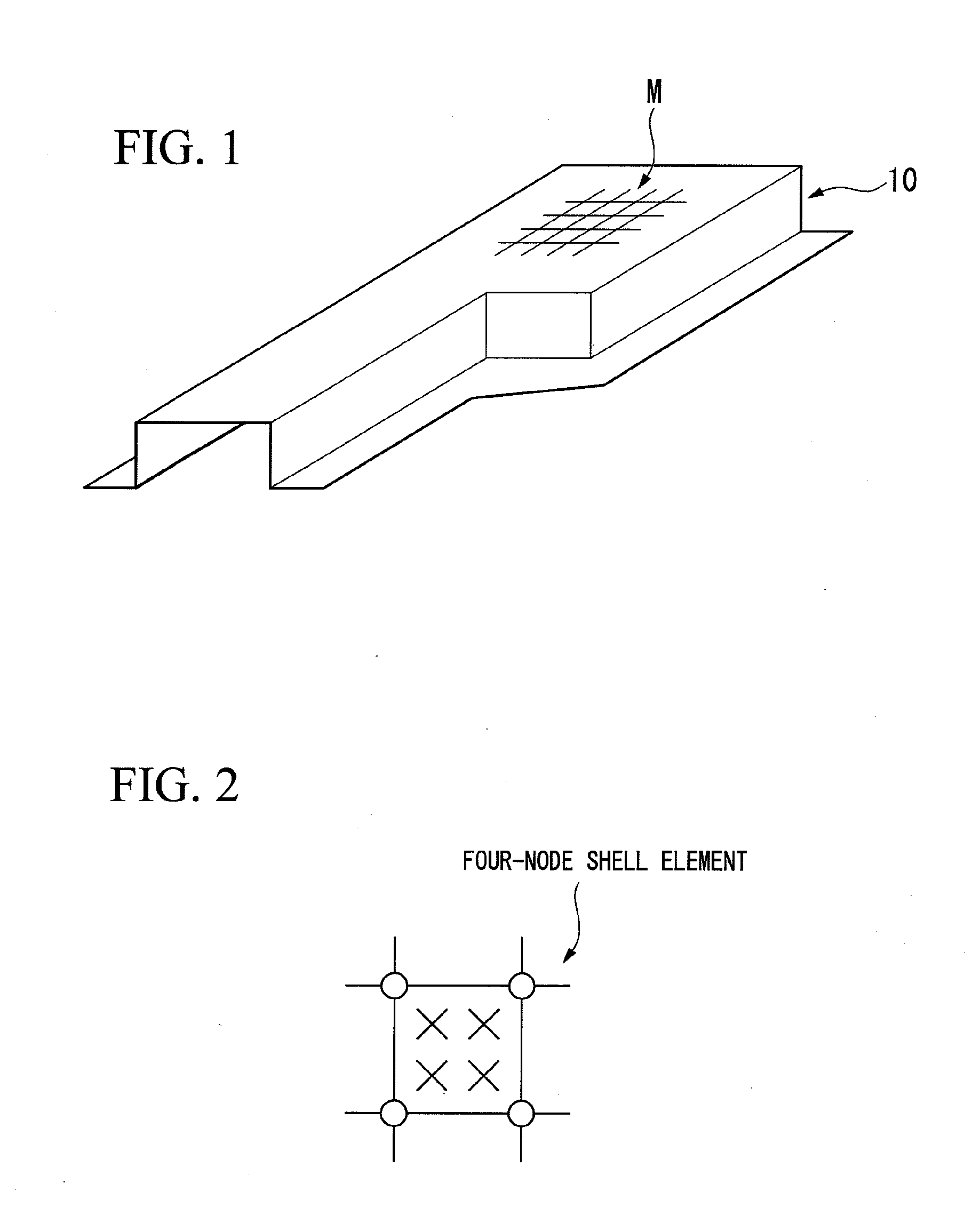
[0078]FIG. 1 is a schematic perspective view of an exemplary configuration at a bottom dead point of the tool of a thin metal sheet of interest for forming simulation (i.e., a forming target configuration) according to an embodiment of the present invention.

[0079]FIG. 1 includes a mesh area M representing a finite element on a thin metal sheet 10. A four-node shell element as illustrated in FIG. 2 is used herein as the finite element. The four-node shell element has six degrees of freedom with each node being referred to in a global coordinate system as represented by the following Equation (1). Each integration point has three components of plane stress as represented by the following Equation (2). Although not illustrated, the integration points are located in several layers (five in the present embodiment) in a thickness direction of the thin metal sheet.

Degree of freedom of nodes: {u v w θx θy...

second embodiment

[0110]Referring now to FIGS. 9 to 14, the present invention will be described in detail.

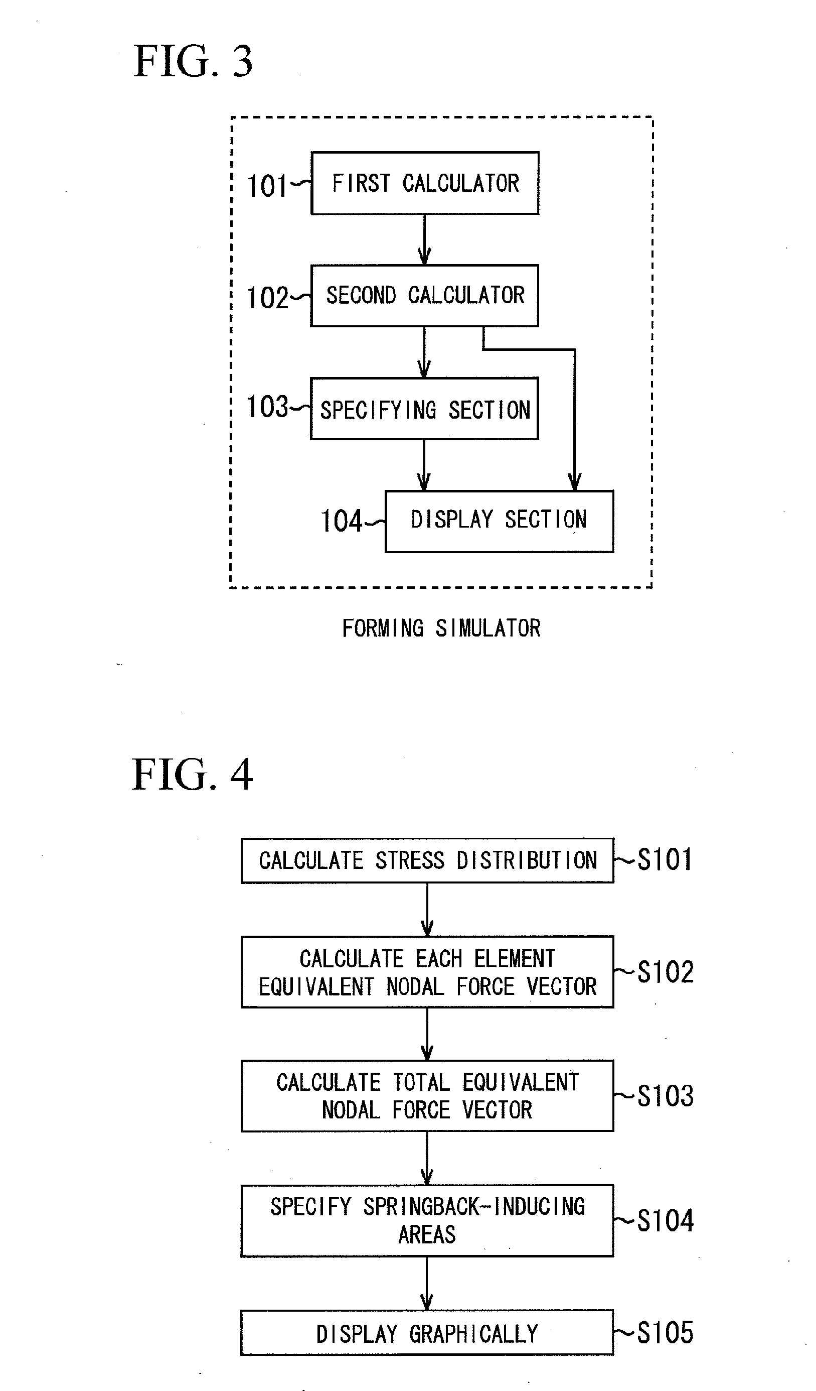
[0111]First, a total equivalent nodal force vector {f} is calculated as in the first embodiment regarding the finite element set in the thin metal sheet 10 using Equations (1) to (4). The total equivalent nodal force vector {f} is represented as an external force vector, as illustrated in the following Equation (5) using a stiffness matrix [K] and specific nodal displacement (ui) in order to estimate springback.

[K]{u}={f}  (5)

[0112]Then, after suitable constraint conditions are given, an inverse matrix [K]−1 of the stiffness matrix [K] is calculated by an ordinary method. The springback amount (u) of the entire product can be obtained as represented in the following Equation as an ordinary method.

{u}=[K]−1{f}  (6)

[0113]The specific nodal displacement (ui) for evaluation of springback can be calculated as represented in the following Equation.

{⋮ui⋮}=[⋮…⋮ki1-1…kiN-1⋮…⋮]{f1⋮fN}ui=∑j=1Nkij-1fj(7)

[011...

third embodiment

[0139]Referring now to FIGS. 15 to 20, the present invention will be described in detail.

[0140]First, as in the second embodiment, regarding the finite element set in the thin metal sheet 10, specific nodal displacement (ui) is calculated using Equations (1) to (7) for evaluation of springback. The specific nodal displacement for evaluation of the calculated springback is considered herein as reference first displacement (ui(1)).

[0141]The element equivalent nodal force vector {f}e calculated for each element is then subtracted from the total equivalent nodal force vector {f} to obtain a corrected equivalent nodal force vector {f′}.

Corrected total equivalent nodal vector: {f′}={f}−{f}e  (8)

[0142]The element equivalent nodal force vector {f}e may be calculated using Equation (3) or using only specific components, for example, in-plane force and moment. Since the purpose herein is to obtain the contribution of the element with respect to springback as described later, a value obtained ...


PUM

PropertyMeasurementUnit
elastic-plasticaaaaaaaaaa
stress tensoraaaaaaaaaa
elastic-aaaaaaaaaa

Abstract

A forming simulation method of an elastic-plastic material, which includes: calculating an element equivalent nodal force vector from stress tensor using a finite element method for one or a plurality of finite elements of a target configuration of the elastic-plastic material; and calculating the total equivalent nodal force vector of areas by integrating the element equivalent nodal force vector for the calculated one or more finite elements over all the areas or specified areas of the elastic-plastic material.

Description

TECHNICAL FIELD OF THE INVENTION[0001]The present invention relates to forming simulation method, forming simulator, program and a recording medium therefor and a simulation-based forming method. More particularly, the present invention relates to forming simulation of elastic-plastic materials such as steel sheets, and aluminum sheets, and plastic materials and composite materials, and a simulation-based forming method.[0002]Priority is claimed on Japanese Patent Application Nos. 2008-252730, filed Sep. 30, 2008, and 2008-253278, filed Sep. 30, 2008, the content of which is incorporated herein by reference.BACKGROUND ART[0003]Automobile parts and home electric product parts have often been press-formed from thin metal sheets, such as steel sheets and aluminum sheets, to a predetermined configuration using upper and lower tools having projections and indentations. Recently, materials of higher strength and reduced thickness have been employed in order to provide lightweight press-fo...

Claims


Application Information

Patent Timeline
Patent Type & Authority Applications(United States)
IPC IPC(8): G06F17/50G06G7/48G06F17/10
CPCB21D22/00G06F2217/42G06F2217/41G06F17/5018G06F30/23G06F2113/22G06F2113/24
Inventor SUZUKI, NORIYUKIARIGA, TAKASHIUENISHI, AKIHIROYONEMURA, SHIGERU
Owner NIPPON STEEL CORP
Why Eureka
Try Eureka