
Device for the metered addition of fuel

a technology of fuel addition and metering device, which is applied in the direction of auxillary pretreatment, separation process, filtration separation, etc., can solve the problems of burning off of soot stored in the particle filter, and achieve the effect of reducing pressure peaks, quick detection, and lessening the danger of damage to the sensor

Inactive Publication Date: 2011-07-21
ROBERT BOSCH GMBH
View PDF3 Cites 3 Cited by
  • Summary
  • Abstract
  • Description
  • Claims
  • Application Information

AI Technical Summary

Benefits of technology

[0002]According to the invention, a metering device for fuel, in particular diesel fuel, upstream of the oxidation catalytic converter of an exhaust system of internal combustion systems, is proposed, and a closing valve and / or a metering valve and an injection valve are integrated, downstream of a supply device for fuel, into a fuel line in which at least one device for damping pressure fluctuations is provided in the vicinity of the metering device. With the aid of the device for damping, the pressure peaks or pressure signals that occur in the metering device or in the exhaust system can be damped in such a way that no damage occurs to the individual assemblies or to the pressure sensors. This also means that pressure peaks are reduced so sharply that, while they are effective and are sensed at the individual sensors, nevertheless they no longer lead to damage to the pressure sensor. Thus on the one hand damage to the sensor components is precluded; on the other, it is ensured that an adequate pressure signal, which can be evaluated by the sensor system, is available.
[0003]It is advantageous that a metering unit for fuel, in particular for diesel fuel, which is connected to the device for damping pressure fluctuations is integrated with the metering device.
[0004]It is also advantageous that the device for damping pressure fluctuations is downstream of a low-pressure circuit or of a pump for fuel supply. In this way, the device for damping pressure fluctuations can readily be accommodated inexpensively in this system, for instance inside a metering unit of the metering device for fuel.
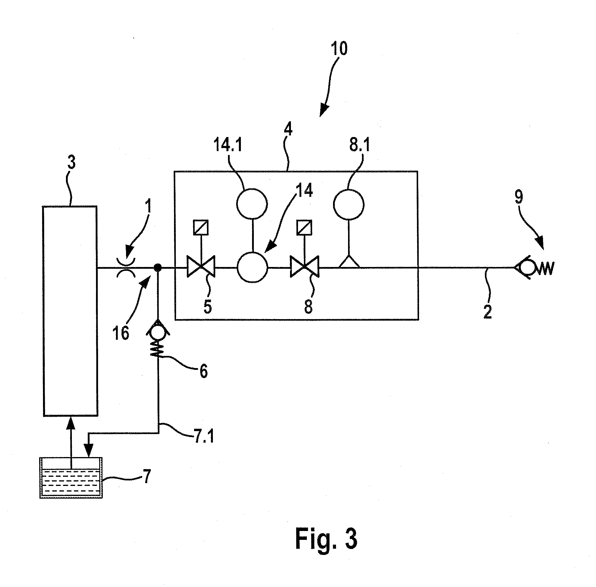
[0006]It is also advantageous that the device for damping pressure fluctuations is provided in a housing part of the metering unit and has a container, or an expansion part, in the fuel inlet or in the fuel line, or in the housing part for receiving an additional fuel volume, and that the container or the expansion part for receiving an additional fuel volume is integrated into the metering unit between the closing valve and the metering valve. In this way, pressure fluctuations that occur can be damped and quickly detected, and then made available to the control device for continuous fuel supply. As a result, malfunctions or defects in the fuel line can be ascertained at that point, and depending on the magnitude of the problem, the fuel supply can be interrupted until such time as the problem in the fuel line is eliminated. Moreover, the container or the expansion part for receiving a fuel volume can advantageously be part of a valve block or of the fuel inlet or of the fuel line and can be formed for example by a widening of the tube.
[0007]It is also advantageous that at the fuel inlet or at the fuel line, the metering valve is provided with at least one pressure sensor downstream of the closing valve. As a result, it is advantageously possible to diagnose a torn-off line or a leak in the line. Optionally, the metering can be controlled even in the absence of the pressure sensor.
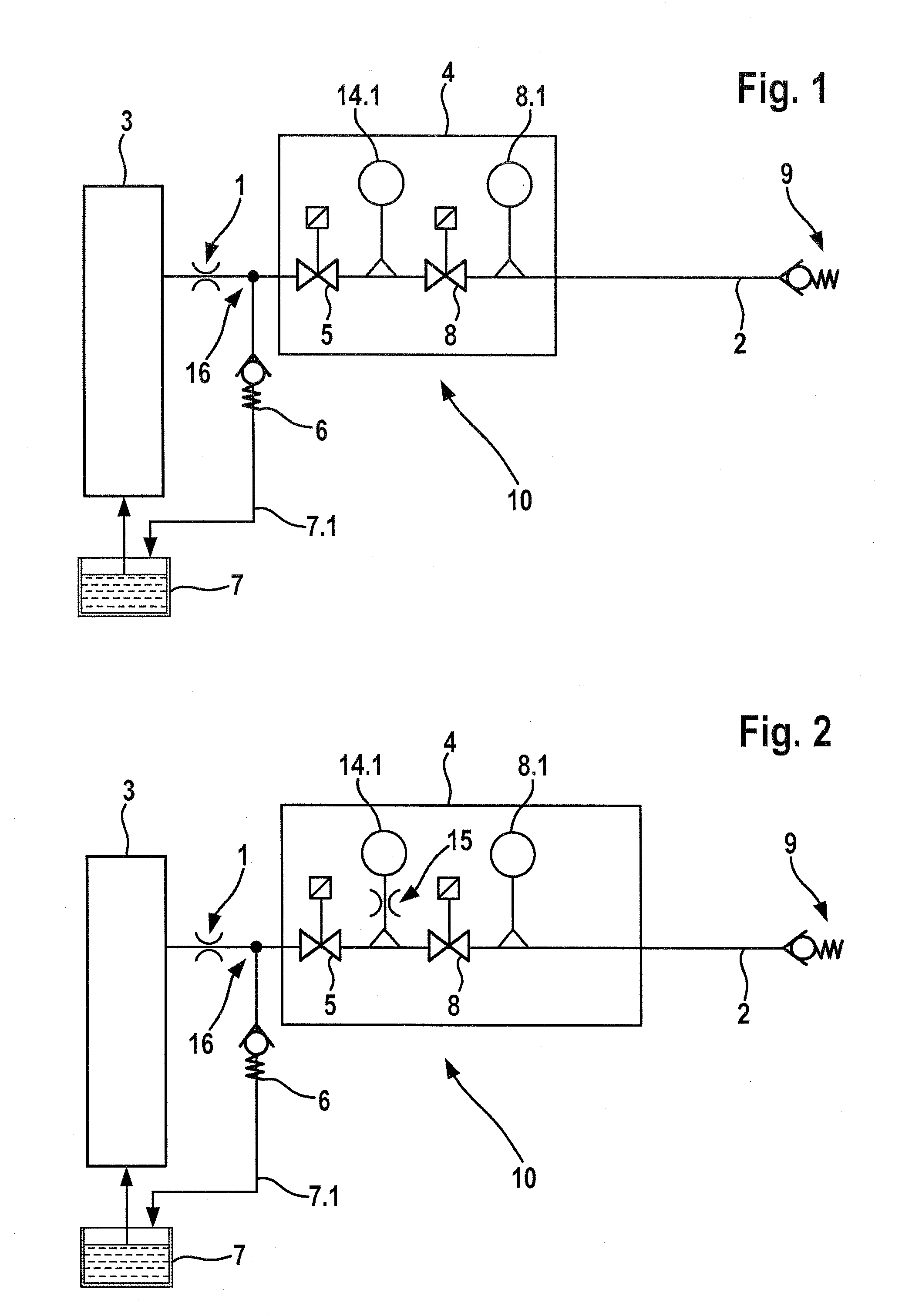
[0008]It is moreover advantageous that between the closing valve and the metering valve, at least one damping throttle restriction having a pressure sensor is connected to the fuel inlet. The at least one throttle restriction reduces pressure peaks upstream of the sensor and thus lessens the danger of damage to the sensor. From the pressure upstream of the metering valve and the required fuel quantity, the opening time of the metering valve can advantageously be calculated; optionally, there is the possibility of using a temperature sensor, in order to make a temperature-dependent correction of the quantity.

Problems solved by technology

In the process, soot stored in the particle filter burns off.

Method used


Image

  • Device for the metered addition of fuel
  • Device for the metered addition of fuel
  • Device for the metered addition of fuel

Examples


Embodiment Construction

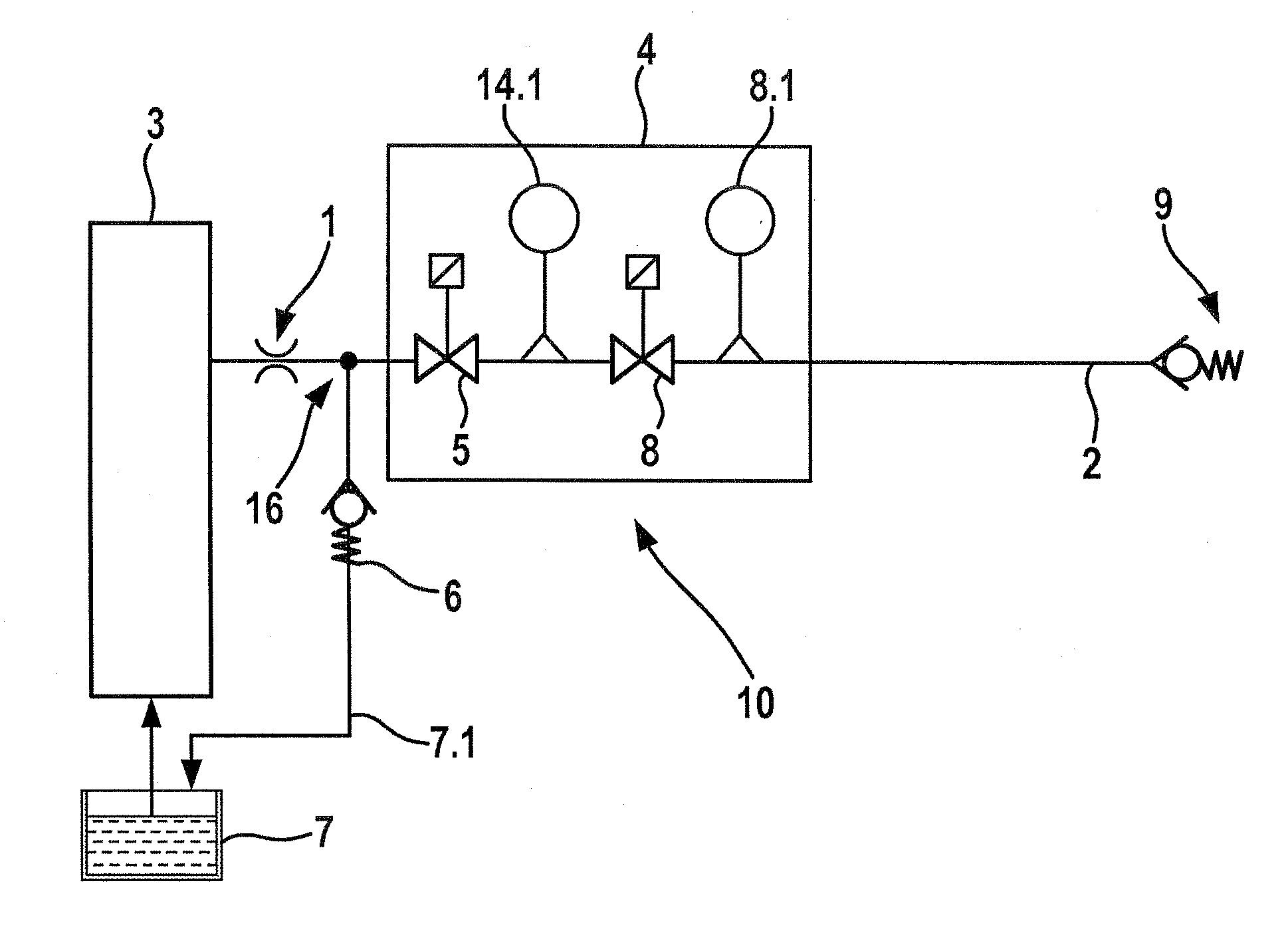
[0014]It can be seen from the view in FIG. 1 that the fuel supply to a metering device 10 is effected via a pickup point at a low-pressure circuit 3 of a fuel injection system, not further shown in FIG. 1, of an internal combustion system of the vehicle. Via a throttle restriction 1 provided in a fuel inlet 16, fuel flows to a metering unit 4, which in FIGS. 1-3 is represented by a rectangular outline and is accommodated in a housing part, not shown in detail in the drawing.

[0015]In regeneration pauses, a closing valve 5 provided downstream of the throttle restriction 1 interrupts the inflow of fuel, especially diesel fuel, to the metering unit 4. With the closing valve 5 closed, the entire fuel volume flows back into a tank 7, via an overflow valve 6, embodied for example as a check valve. The overflow valve 6 is provided in a return line 7.1, which is connected between the throttle restriction 1 and the metering unit 4 to the fuel inlet 16 and which discharges into the tank 7.

[001...


PUM

PropertyMeasurementUnit
Pressureaaaaaaaaaa
Volumeaaaaaaaaaa

Abstract

The invention relates to a metering device for fuel, particularly diesel fuel, upstream of an oxidation catalyst of an exhaust gas system of an external combustion engine. According to the invention, downstream of a supply device for fuel, a closing valve and / or a metering valve and an injection valve are integrated in a fuel line. In the region of the metering device, at least one throttle restriction for damping pressure fluctuations is provided.

Description

PRIOR ART[0001]With a device for metering fuel, in particular diesel fuel, upstream of an oxidation catalytic converter, which device is known by the name Departronic, a fuel metering system for regenerating particle filters is offered particularly for heavy utility vehicles. The system makes it possible, with a purposeful injection of fuel, particularly diesel fuel, into the exhaust gas, to regenerate the particle filter by burning off the soot particles that have been deposited there. An expensive coating of the filter or an additional tank for an additive are not needed. The device for metering fuel, in particular diesel fuel, upstream of the oxidation catalytic converter is integrated with a low-pressure fuel circuit. It injects a precisely metered quantity of fuel into the exhaust system upstream of the oxidation catalytic converter, without compressed-air reinforcement. The exhaust gas temperature as it flows through the oxidation catalytic converter rises sharply in the exhau...

Claims


Application Information

Patent Timeline
IPC IPC(8): F01N3/025F01N3/20
CPCF01N3/0253F01N3/36F01N2260/04F01N2610/1473F01N2610/14F01N2610/1446F01N2610/03
Inventor BOERNER, MARKUSBENITSCH, JENS
Owner ROBERT BOSCH GMBH
Learn More