Carbon nanotube vacuum gauges with wide-dynamic range and processes thereof

a vacuum gauge and carbon nanotube technology, applied in the direction of fluid pressure measurement, instruments, measurement devices, etc., can solve the problems of inability to obtain a wide dynamic range with these transducers, and inability to integrate with many vacuum-encased si-based micro-cavity applications, etc., to achieve substantial pressure sensitivity, reduce thermal conduction dimensionality, and high temperature coefficient of resistivity ratio

Inactive Publication Date: 2011-07-21
CALIFORNIA INST OF TECH
View PDF14 Cites 17 Cited by
  • Summary
  • Abstract
  • Description
  • Claims
  • Application Information

AI Technical Summary

Benefits of technology

[0007]The present invention is directed to a miniature thermal conductivity gauge and process employing a carbon single-walled-nanotube. The gauge operates on the principle of thermal exchange between a voltage-biased carbon nanotube and the surrounding gas at low levels of power and low temperatures to measure variations in electrical conductance, measured by current at constant voltage, indicative of the magnitude of vacuum across a wide dynamic range. Due to the ...

Problems solved by technology

Such gauges are physically large (volume ˜10 cm3), prohibiting their integration with many vacuum-encased Si-based micro-cavity applications (vacuum microelectronics, micro-eletromechanical-systems (MEMS) such as gyroscopes and RF switches).
As a result of their large thermal mass, such thermocouple gauges are inherently slow, and also operate at substantial power levels and h...

Method used


Image

  • Carbon nanotube vacuum gauges with wide-dynamic range and processes thereof
  • Carbon nanotube vacuum gauges with wide-dynamic range and processes thereof
  • Carbon nanotube vacuum gauges with wide-dynamic range and processes thereof

Examples


Embodiment Construction

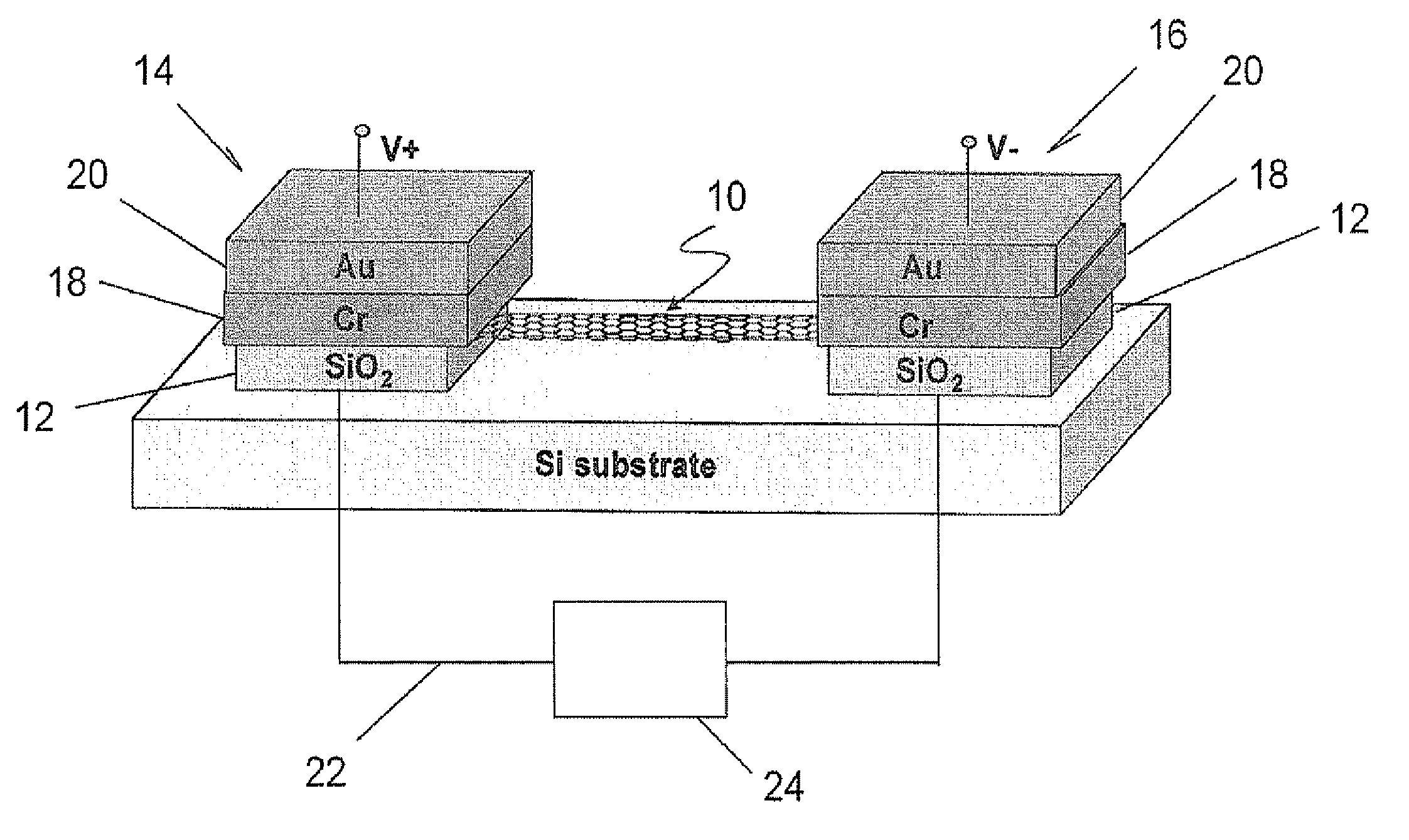
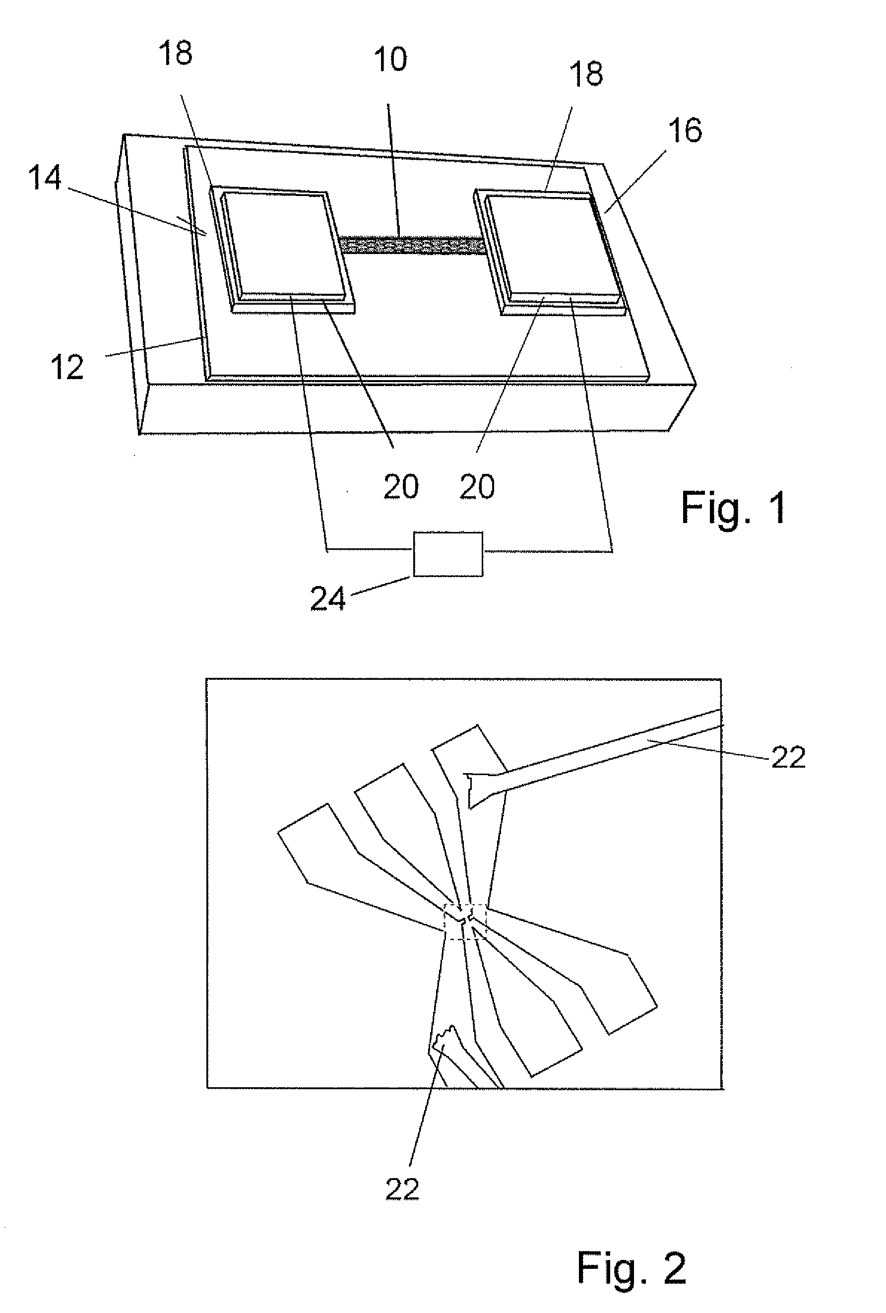
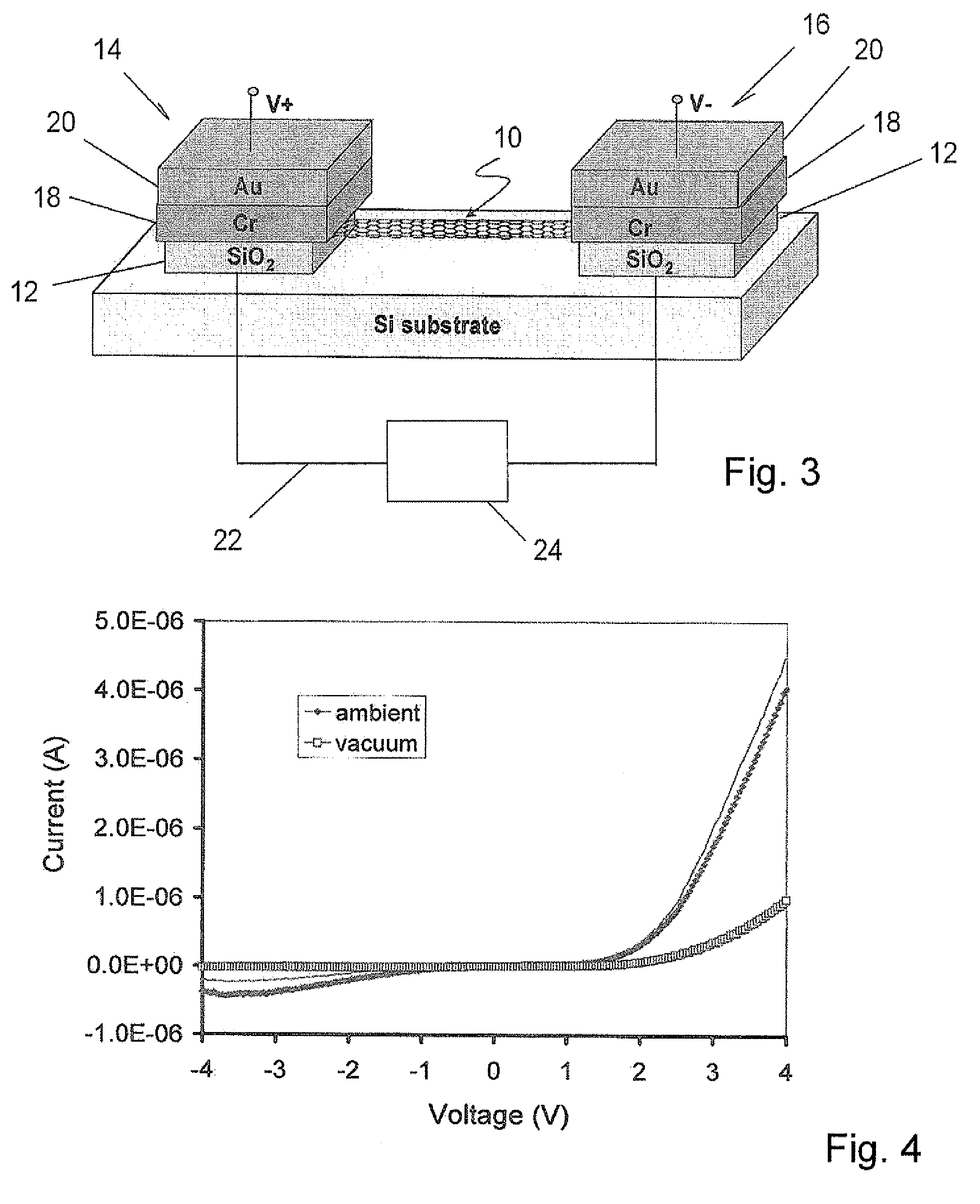
[0022]A miniature carbon nanotube (CNT) based thermal conductivity gauge is schematically illustrated in FIG. 1. A single-walled-nanotube (SWNT) 10 is supported on an SiO2 substrate 12. Two Au / Cr electrodes 14, 16 formed on the substrate 12 receive the ends of the SWNT 10. The SiO2 substrate 12 may be etched away beneath the SWNT 10 to suspend the SWNT 10 from the electrodes 14, 16 in separation from the substrate 12. The typical tube length of the SWNT 10 between electrodes is 5 μm to 10 μm. The miniature CNT-based thermal conductivity gauge has a volume ˜10−4 cm3 and operates at low power (nW-μW) and low temperatures. The CNT gauge exhibits a wide dynamic range of 760 Torr-10−6 Torr.

[0023]In fabrication, the starting substrate is a thermally oxidized Si wafer 12. Patterned chemical vapor deposited growth of the SWNT 10 employs Fe-catalyst. Reference is made to J. Kong, H. Soh, A. Cassell, C. F. Quate, and H. Dai, “Synthesis of individual single walled carbon nanotubes on patterne...


PUM


Abstract

A miniature thermal conductivity gauge employs a carbon single-walled-nanotube. The gauge operates on the principle of thermal exchange between the voltage-biased nanotube and the surrounding gas at low levels of power and low temperatures to measure vacuum across a wide dynamic range. The gauge includes two terminals, a source of constant voltage to the terminals, a single-walled carbon nanotube between the terminals, a calibration of measured conductance of the nanotube to magnitudes of surrounding vacuum and a current meter in electrical communication with the source of constant voltage. Employment of the nanotube for measuring vacuum includes calibrating the electrical conductance of the nanotube to magnitudes of vacuum, exposing the nanotube to a vacuum, applying a constant voltage across the nanotube, measuring the electrical conductance of the nanotube in the vacuum with the constant voltage applied and converting the measured electrical conductance to the corresponding calibrated magnitude of vacuum using the calibration. The nanotube may be suspended to minimize heat dissipation through the substrate, increasing sensitivity at even tower pressures.

Description

CROSS-REFERENCE TO RELATED APPLICATIONS[0001]This application claims priority to Provisional Application Ser. No. 61 / 005,064, filed Nov. 30, 2007, the disclosure of which is incorporated herein by reference.STATEMENT REGARDING FEDERAL SPONSORSHIP[0002]The invention described herein was made in the performance of work under a NASA contract, and is subject to the provisions of Public Law 96-517 (35 USC 202) in which the Contractor has elected to retain title.BACKGROUND OF THE INVENTION[0003]With exceptional materials properties, carbon nanotubes offer tremendous opportunities for scientific and technological exploration. Since their discovery more than a decade ago their use in electronics applications continues to grow, as exemplified by CNT-based field-effect-transistors (FETs) memory devices and tunable oscillators.[0004]Recently, carbon nanotubes have also been applied to pressure sensing based on piezoresistance, opening up yet another promising application of nanotubes. For piez...

Claims


Application Information

Patent Timeline
IPC IPC(8): G01L21/12
CPCG01L21/12
Inventor MANOHARA, HARISHKAUL, ANUPAMA B.
Owner CALIFORNIA INST OF TECH
Why Eureka
Try Eureka