Isolated current regulated DC-DC converter

a dc-dc converter and current-regulated technology, applied in the direction of dc-dc conversion, power conversion systems, instruments, etc., can solve the problems of slow response line and load change regulation of the flyback dc-dc converter, hard to meet high performance and low cost selection for the primary side switch, etc., to achieve high switching frequency, high efficiency, and low switching loss on two switches

Inactive Publication Date: 2011-07-21
WENG DA FENG +1
View PDF6 Cites 8 Cited by
  • Summary
  • Abstract
  • Description
  • Claims
  • Application Information

AI Technical Summary

Benefits of technology

[0015]According to an advantage of the instant invention, the voltage stress on two switches in two modified out of phase forward DC-DC converters is independent of the input voltage Vin, and voltage stress on two switches and output diodes is dependent on the output voltage and the turns-ratio of the switching transformer. According to an advantage of the instant invention, the current stress of two switches in two modified out of phase forward DC-DC converters can be adjusted with the turns-ratio of the switching transformer and the output load current.
[0016]According to an advantage of the instant invention, two switching transformers in two modified out of phase forward DC-DC converters can be replaced with one switching transformer. According to an advantage of the instant invention, the switching transformer can operate in both the first and third quadrants with no DC bias. It is different with one in the forward DC-DC converter. In the forward DC-DC converter, the switching transformer only operates in the first quadrant and has DC bias. The size of the switching transformer can be half of one for regular forward DC-DC converter. According to an advantage of the instant invention, the leakage energy in the switching transformer can be lossless fed to the output load and it makes the invented converter to operate in high efficiency and high switching frequency.
[0017]According to an advantage of the instant invention, two switches in two modified out of phase forward DC-DC converters can be turned on in zero voltage switching (ZVS) condition and the switching loss on two switches can be much low. According to an advantage of the instant invention, two switches can operate in 50% duty-cycle with out of phase. According to an advantage of the instant invention, two switches can be droved in low cost self oscillation.
[0018]According to an advantage of the instant invention, the switch in step down current regulator can turn on and off in wide duty-cycle ratio from 0% to 100%. According to an advantage of the instant invention, the dynamic regulation performance of the invented isolated high performance-cost ratio current regulated DC-DC converter is much closed to one of the regular step down DC-DC converter. Due to the switching transformer in the invented isolated high performance-cost ratio current regulated DC-DC converter, the step down switch SA can be droved in common ground.

Problems solved by technology

Due to discontinuous energy transfer, it makes the regulation of the flyback DC-DC converter slow and hard to fast response line and load change.
For higher input voltage application, the selection for the primary side switch is hard to meet both high performance and low cost.

Method used


Image

  • Isolated current regulated DC-DC converter
  • Isolated current regulated DC-DC converter
  • Isolated current regulated DC-DC converter

Examples


Embodiment Construction

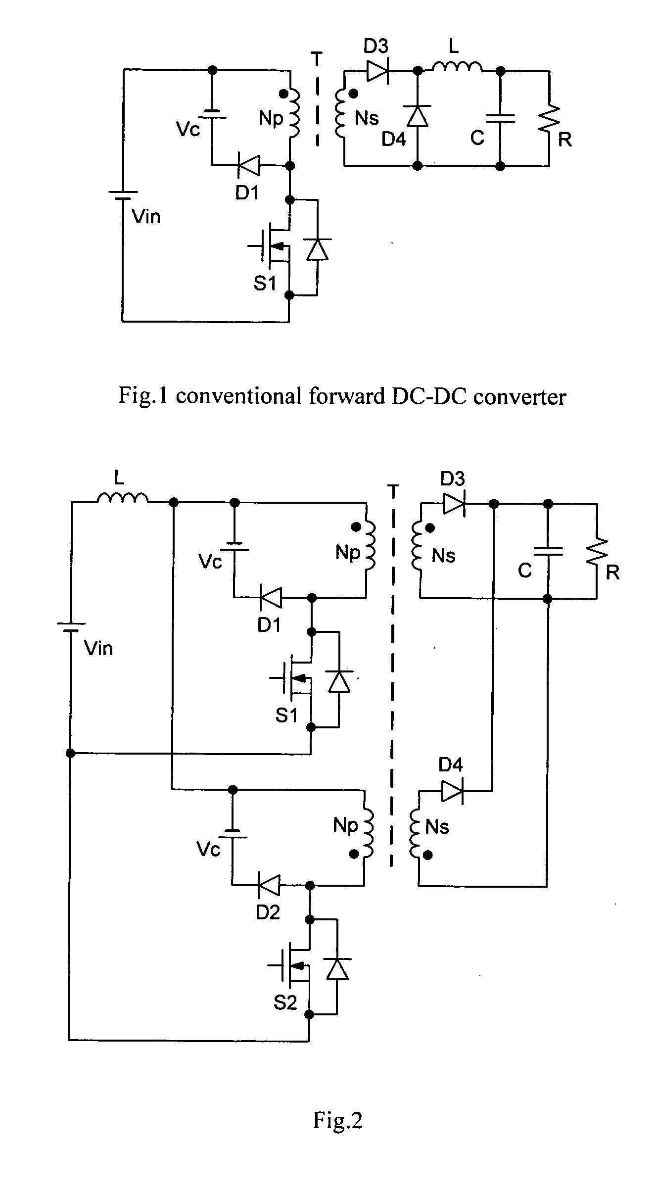
[0034]The conventional forward DC-DC converter is shown in FIG. 1. Vc is a clamping voltage. In general, Vc=Vin. The primary switch's voltage stress is twice of the input voltage. The components' current stress is Ns*Io / Np, Io is the output current.

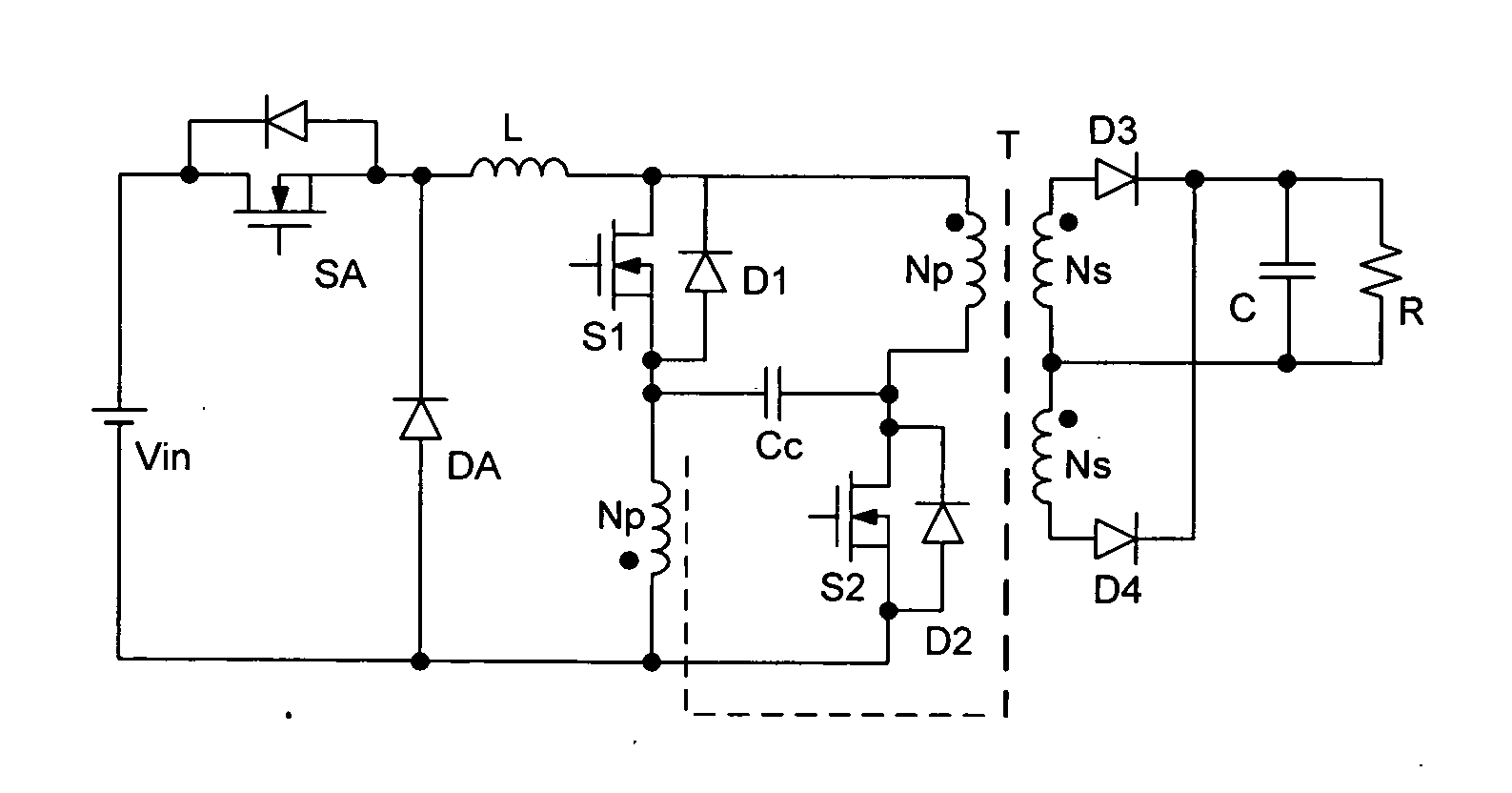
[0035]In FIG. 1, if the inductor L is moved from the secondary to the primary, in order to keep the inductor current continuous, an additional auxiliary forward converter is added and shown in FIG. 2. As shown in FIG. 2, switches S1 and S2 turns on alternately, that is, as S1 turns on, S2 turns off, vice verse. The clamping voltage Vc=Np*Vo / Ns and Vo is the output voltage.

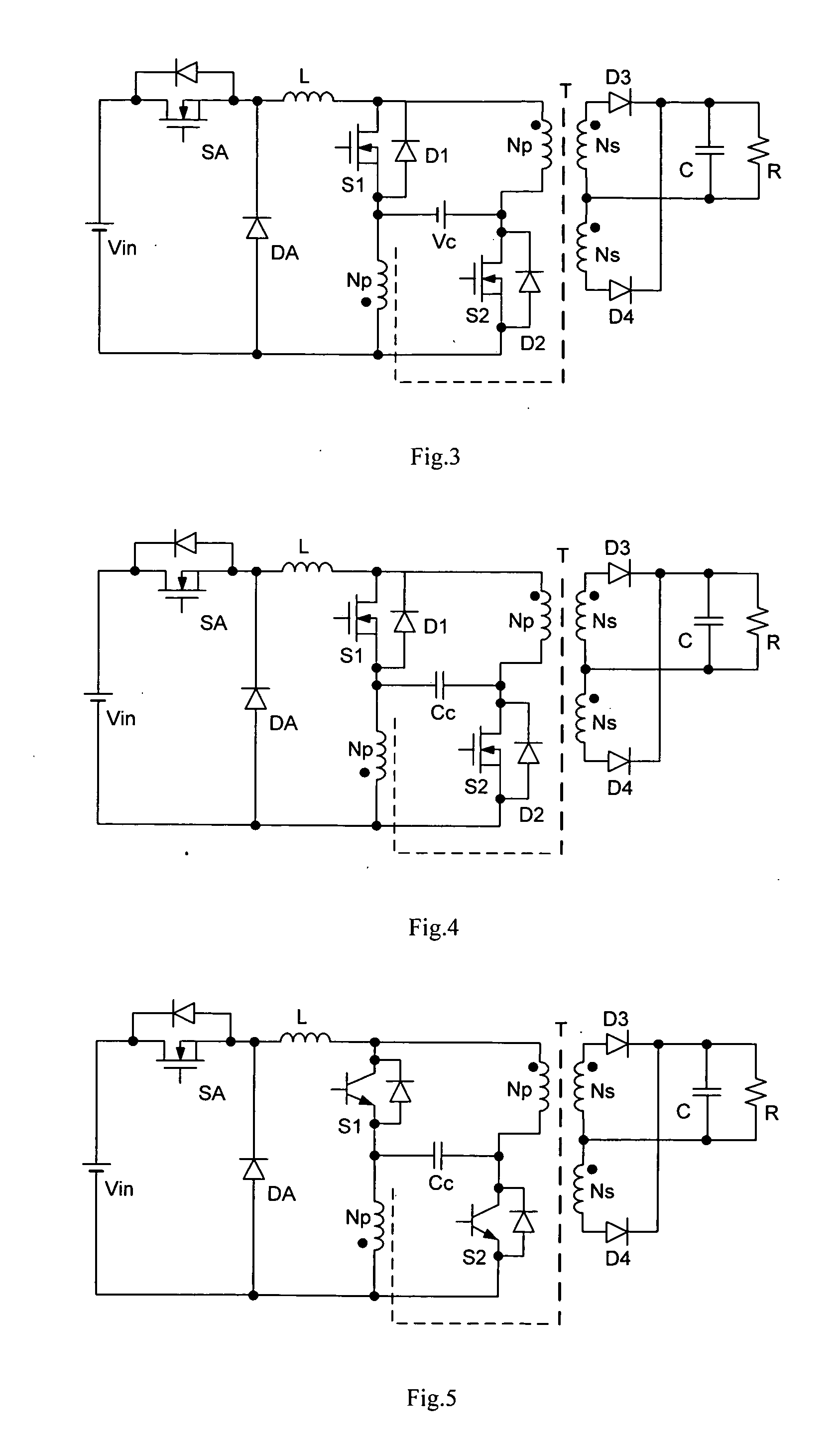
[0036]Due to S1 and S2 turn on and off alternately, the inductor L current can be transferred through S1, S2, D3, D4 and the switching transformer T to the load. In this case, S1 and S2's voltage stress is 2×Vc=2×Np*Vo / Ns. It is obvious that as long as the inductor L current can be controlled, the output current and voltage of the DC-DC converter can be controlled. Becau...


PUM


Abstract

The isolated current regulated DC-DC converter is composed of the step down switch SA, free wheel diode DA, step down inductor L, switches S1 and S2, capacitor Cc to absorb the leakage energy of the switching transformer, output diodes D3 and D4, output filter capacitor C and the switching transformer T; one terminal of the step down inductor L is connected with the step down switch SA and free wheel diode DA, and other terminal of the step down inductor L is connected with one of primary windings of the switching transformer and switch S1 or S2; two primary windings of the switching transformer are respectively connected with switches S1 and S2 in series; two primary winding and switch S1 or S2 branches are paralleled and respectively connected with the free wheel diode DA and the step down inductor L; the free wheel diode DA is series with the step down switch SA and they connect with the input voltage Vin; the capacitor Cc to absorb the leakage energy of the switching transformer is respectively connected with switches S1 and S2; the full wave rectifier is composed of two secondary windings and output diodes D3, D4; the output capacitor C is paralleled with the output load. The converter has the same voltage and current stress and dynamic regulation as one of regular step down DC-DC converter. It also has function to isolate the input and the output with the switching transformer. In practical application, due to the freedom of the switching transformer's turns-ratio, it is possible to make the isolated current regulated DC-DC converter to operate in much better condition than one for the regular step down DC-DC converter and to have higher efficiency.

Description

TECHNICAL FIELD[0001]Embodiments of the invention described herein relate generally to isolated DC-DC converter topology, and more particularly to high performance low cost isolated current regulated DC-DC converter.BACKGROUND OF THE INVENTION[0002]In a lot of DC-DC converter application, due to application requirement, it needs to isolate the DC-DC converter's input and output. In general, it can be implemented with a switching transformer. In other application, due to higher voltage ratio of the input to output of the DC-DC converter application, in order to increase the efficiency of the DC-DC converter, in general, a suitable turns-ratio of the high switching frequency transformer is used to make the DC-DC converter operation in optimum and to increase the efficiency. In most of this kind low and middle power level application, flyback and forward DC-DC converters are the main power topology structures. With them, it is possible to build a system with less component account, but...

Claims


Application Information

Patent Timeline
Patent Type & Authority Applications(United States)
IPC IPC(8): H02M3/335
CPCH02M3/156H02M3/33538H02M1/007
Inventor WENG, DA FENGWEI, QI CUI
Owner WENG DA FENG
Why Eureka
Try Eureka