Magnetic resonance imaging apparatus, and breath-holding imaging method

Active Publication Date: 2011-07-28
FUJIFILM HEALTHCARE CORP
View PDF10 Cites 15 Cited by
  • Summary
  • Abstract
  • Description
  • Claims
  • Application Information

AI Technical Summary

Benefits of technology

[0016]According to the MRI apparatus and the breath-holding imaging method of the present invention, it is possible to set the optimal imaging conditions of breath-holding measurement according to the subject without extension of the imaging time or the sacrifi

Problems solved by technology

In this case, if echo data with a change in the shape of the subject caused by breathing movement is arrayed in the same

Method used


Image

  • Magnetic resonance imaging apparatus, and breath-holding imaging method
  • Magnetic resonance imaging apparatus, and breath-holding imaging method
  • Magnetic resonance imaging apparatus, and breath-holding imaging method

Examples


first embodiment

[0043]Next, a first embodiment of the MRI apparatus and the breath-holding imaging method of the present invention will be described. In the present embodiment, corresponding to imaging conditions of breath-holding measurement which are input and set according to the subject, one scan is divided into one or more breath-holding measurements and free-breathing measurements and a region of the k space measured in the breath-holding measurement is controlled. Alternatively, one scan may be divided into only two or more breath-holding measurements with no free-breathing measurement. Preferably, low-frequency data of the k space is measured during the breath-holding measurement period. As imaging conditions for the breath-holding measurement, the number of times of breath holding and a breath-holding time are included.

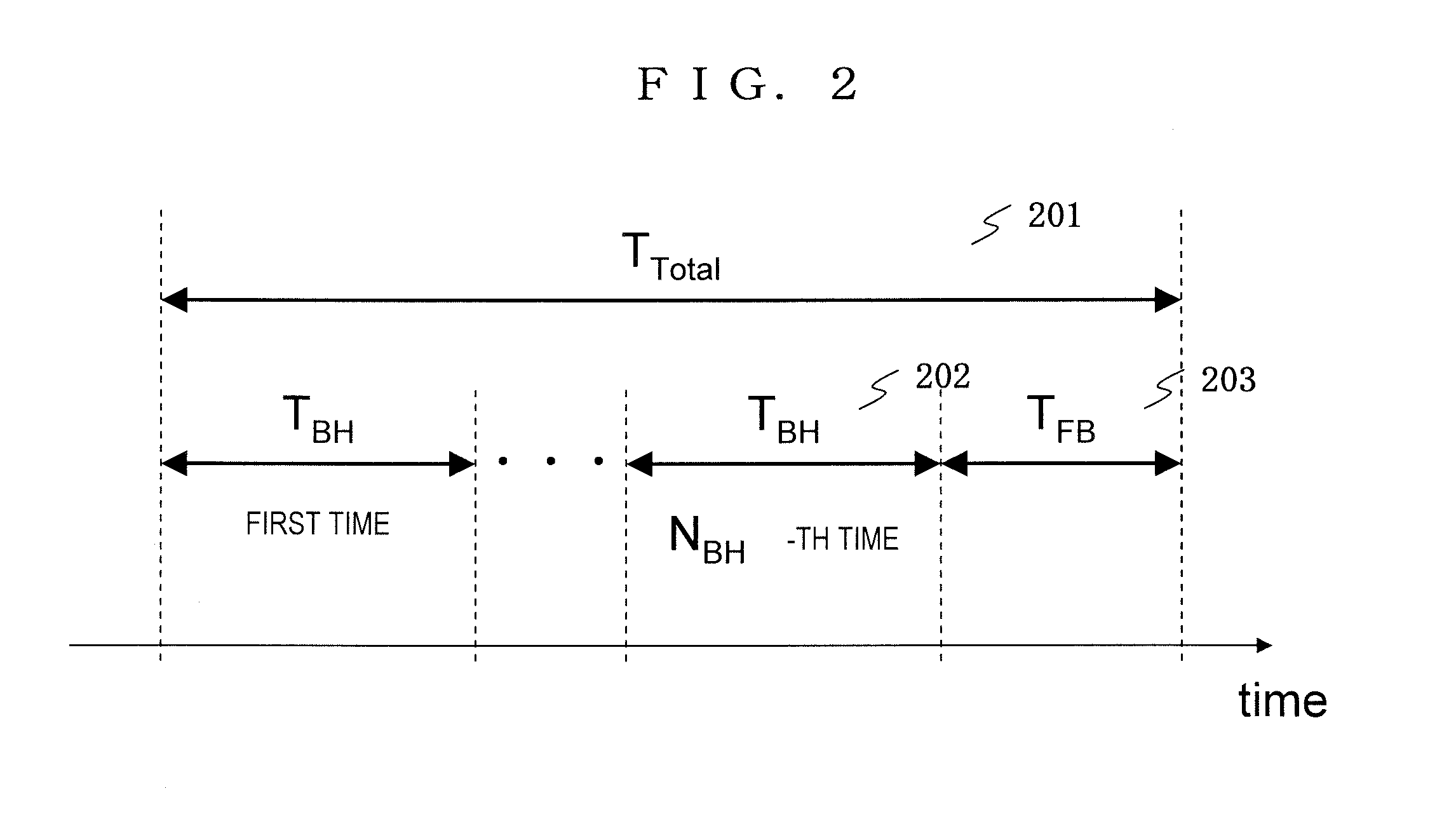
[0044]Hereinafter, the present embodiment will be described on the basis of FIGS. 2 to 4. FIG. 2 is a time chart showing the concept of the present embodiment, FIG. 3 is a f...

second embodiment

[0090]A second embodiment of the MRI apparatus and the breath-holding imaging method of the present invention will be described. In the first embodiment described above, TBH was set as a breath-holding time per time [second]. In the present embodiment, however, a total breath-holding time is included as imaging conditions for breath-holding measurement and TBH is set as a total time of “NBH” breath holding. That is, an upper limit of the burden in breath holding of the subject is set as the total breath-holding time TBH. Hereinafter, only a different point from the first embodiment will be described, and an explanation regarding the same point will be omitted.

[0091]FIG. 8 is a time chart showing the concept of the present embodiment, and FIG. 9 is a flow chart showing an example of the process flow of the present embodiment.

[0092]As shown in FIG. 8, in the present embodiment, first, a single scan with a total measurement time of TTotal [second] (801) is divided into a breath-holding...

third embodiment

[0103]A third embodiment of the MRI apparatus and the breath-holding imaging method of the present invention will be described. In each of the embodiments described above, there was no particular limitation on a pulse sequence. In the present embodiment, however, k space data is measured slice by slice when the present invention is applied to imaging using SSFP (Steady State Free Precession) sequence. Moreover, in breath-holding measurement, the low-frequency data of the k space corresponding to each slice is measured.

[0104]The SSFP sequence is a sequence in which an RF pulse is irradiated at short intervals (TR) and an echo signal is repeatedly measured from transverse magnetization shifted to the steady state (for example, JP-A-2004-329268. An example of filling the echo data into the k space in the SSFP sequence is shown in FIG. 10a. In the SSFP sequence, in many cases, the echo data is measured to fill the k space slice by slice so that the steady state of transverse magnetizati...


PUM


Abstract

In order to make it possible to set the optimal breath-holding imaging conditions according to the subject without extension of an imaging time or the sacrifice of image quality, one scan is divided into one or more breath-holding measurements and free-breathing measurements on the basis of the imaging conditions of a breath-holding measurement, which are input and set according to the subject, and a region of the k space measured in the breath-holding measurement is controlled. Preferably, in the breath-holding measurement, low-frequency data of the k space is measured. Moreover, preferably, imaging conditions of the breath-holding measurement include the number of times of breath holding or a breath-holding time, and the operator can set any of these values.

Description

TECHNICAL FIELD [0001]The present invention relates to breath-holding measurement in a nuclear magnetic resonance imaging (hereinafter, referred to as “MRI”) apparatus which measures a nuclear magnetic resonance (hereinafter, referred to as “NMR”) signal from hydrogen, phosphor, or the like in a subject and images nuclear density distribution, relaxation time distribution, or the like.BACKGROUND ART [0002]The MRI apparatus is an apparatus which measures an NMR signal generated by the subject, especially, the nuclear spins which form human tissue and images the shapes or functions of the head, abdomen, limbs, and the like in a two-dimensional manner or in a three-dimensional manner. In the imaging, different phase encoding and different frequency encoding are given to NMR signals by the gradient magnetic field. Measured NMR signals are reconstructed as an image by two-dimensional or three-dimensional Fourier transform.[0003]The measured NMR signals (hereinafter, referred to as echo s...

Claims


Application Information

Patent Timeline
IPC IPC(8): G01R33/48
CPCA61B5/055G01R33/5602G01R33/56509G01R33/5613G01R33/5607
Inventor KAMADA, YASUHIRO
Owner FUJIFILM HEALTHCARE CORP
Why Eureka
Try Eureka