Gas shower structure and substrate processing apparatus

Active Publication Date: 2011-08-04
TOKYO ELECTRON LTD
View PDF22 Cites 8 Cited by
  • Summary
  • Abstract
  • Description
  • Claims
  • Application Information

AI Technical Summary

Benefits of technology

[0020]In accordance with the present disclosure, the gas shower structure is formed by stacking the base member on the plate-shaped member exposed to the processing atmosphere and supplies the gas as in a shower device. The joining member is provided at the surface of the plate-shaped member on the side of the processing atmosphere, and the plate-shaped member is sandwiched between the joining member and the base member. Further, the elastic member is interposed between the plate-shaped member and the joining member,

Problems solved by technology

Thus, the screw torque needs to be controlled strictly such that the screw 114 is prevented from being excessively tightened or loosened, and assembly errors may lead to non-uniformity of performance (non-uniformity of the pressing force).
Further, when the shower plate 107 is used as an electrode in a plasma process, an electrical conduction becomes poor.
If the thermal conductivity or an electrical conduction become poor, the uniformity of the heat or an electric field between the shower plate 107 and a vicinity thereof is decreased, resulting in deteriorating the uniformity in a surface of the substrate in the plasma process.
Accordingly, the thermal expansion difference between the screw 114 and the ceiling plate 111 causes friction at a contact area S, which results in the above-described problems.
In such a case

Method used


Image

  • Gas shower structure and substrate processing apparatus
  • Gas shower structure and substrate processing apparatus
  • Gas shower structure and substrate processing apparatus

Examples


Embodiment Construction

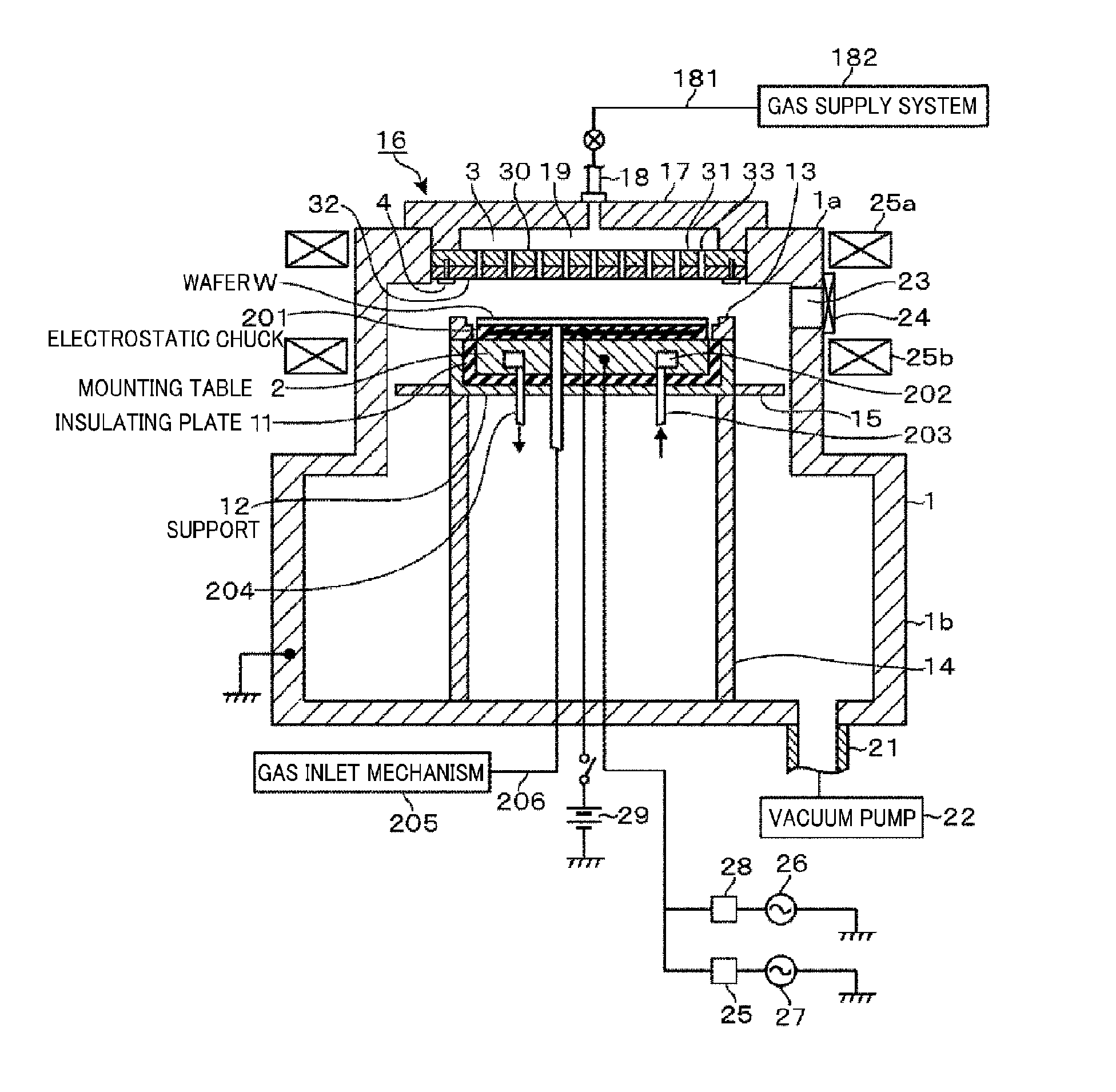
[0033]Hereinafter, an example of a substrate processing apparatus including a gas shower structure in accordance with an embodiment of the present disclosure will be described. FIG. 1 shows an entire configuration of a substrate processing apparatus. This substrate processing apparatus is configured as a reactive ion etching (RIE) plasma etching apparatus. First of all, the entire configuration of the substrate processing apparatus will be briefly described. A reference numeral 1 in FIG. 1 denotes an airtight processing chamber (vacuum chamber) made of, e.g., aluminum. The processing chamber 1 may include a cylindrical upper portion 1a having a small diameter; and a cylindrical lower portion 1b having a large diameter. Provided in the processing chamber 1 is a mounting table 2 for horizontally mounting thereon a semiconductor wafer W (hereinafter, referred to as a “wafer”) as a substrate and the mounting table 2 serves as a lower electrode. The mounting table 2 is made of, e.g., alu...


PUM

PropertyMeasurementUnit
Lengthaaaaaaaaaa
Circumferenceaaaaaaaaaa
Elasticityaaaaaaaaaa

Abstract

Screws 4 are inserted from a bottom surface of a ceiling plate 32 and screwed to a base plate 31, and the ceiling plate 32 and the base plate 31 are press-connected to each other by an elastic restoring force of an elastic member 51 interposed between a head of the screw 4 and the ceiling plate 32. A gap is formed between the head and the ceiling plate 32. Further, a periphery of the head is covered with a cover via a ring-shaped elastic member 52. In another embodiment, a periphery of a base plate 31 is protruded from a periphery of a ceiling plate 32, and the protruded portion of the base plate 31 and a ring-shaped clamp positioned at an outer side of the ceiling plate 32 are joined by screws. Here, an elastic member is interposed between the clamp and the ceiling plate 32.

Description

CROSS-REFERENCE TO RELATED APPLICATION[0001]This application claims the benefit of Japanese Patent Application No. 2010-023509 filed on Feb. 4, 2010 and U.S. Provisional Application Ser. No. 61 / 307,609 filed on Feb. 24, 2010, the entire disclosures of which are incorporated herein by reference.FIELD OF THE INVENTION[0002]The present disclosure relates to a gas shower structure that is disposed so as to face a substrate in an apparatus for performing a process on the substrate by supplying a gas to the substrate.BACKGROUND OF THE INVENTION[0003]As for an apparatus used for manufacturing semiconductor devices, there has been known a so-called single-wafer processing apparatus for performing a process on a substrate one by one. Specifically, the process may include a plasma process such as a CVD (chemical vapor deposition) process or an etching process, or heat treatment such as a thermal CVD process. Generally, since the apparatus is configured to perform such processes under a vacuum...

Claims


Application Information

Patent Timeline
IPC IPC(8): C23F1/08C23C16/00B05B1/18
CPCB05B1/18C23F1/08C23C16/00C23C16/45565H01J37/3244C23C16/5096H01L21/205H01L21/02263H01L21/02274H01L21/0228H01L21/67011H01L21/67098C23C16/455
Inventor HAYASHI, DAISUKEMURAKAMI, KOICHI
Owner TOKYO ELECTRON LTD
Why Eureka
Try Eureka