Discharge Ionization Current Detector

a technology of discharge ionization current and detector, which is applied in the direction of instruments, measurement devices, scientific instruments, etc., can solve the problems of low ionization efficiency, low ionization efficiency of alcohols, aromatic substances, chlorine substances, etc., and achieves the effects of enhancing plasma stability, improving ionization efficiency, and increasing the flow rate of gas passing through the plasma generation area

Active Publication Date: 2011-08-04
SHIMADZU CORP
View PDF6 Cites 22 Cited by
  • Summary
  • Abstract
  • Description
  • Claims
  • Application Information

AI Technical Summary

Benefits of technology

[0035](1) The flow rate of the gas passing through the plasma generation area can be increased to enhance the plasma's stability and also improve the efficiency of ionization caused by the excitation light emitted from the plasma. Meanwhile, when the concentration of the component of interest in the sample gas is low (extremely small), the flow rate of the gas passing through the current detection area can be decreased to lower the dilution ratio and thereby improve the detection sensitivity.
[0036](2) In a field analysis or similar situation where the gas consumption should be decreased to the lowest possible level, the flow rate of the gas passing through the plasma generation area can be lowered within a range where the plasma can be sufficiently generated. For a high-concentration sample, the flow rate of the gas passing through the current detection area can be increased to make the sample more diluted so that it can be detected within a high-linearity detection range.
[0037](3) Only a single detector is needed to appropriately perform measurements according to the purpose and environment of the measurement, the kind and concentration of the sample concerned, or other factors. This detector can perform various measurements with the same level of accuracy and sensitivity as achieved by dedicated detectors.

Problems solved by technology

However, the FID has the following drawbacks: (1) Its ionization efficiency is low, so that its minimum detectable amount is not sufficiently low.
(2) Its ionization efficiency for alcohols, aromatic substances and chlorine substances is low.
(3) It requires hydrogen, which is a highly hazardous substance; therefore, an explosion-proof apparatus or similar kind of special equipment must be provided, which makes the entire system more difficult to operate.
However, it has the following problem.
This is primarily because a higher flow rate of the plasma gas results in a larger amount of heat radiation from the electrode (which is heated by the plasma), thus preventing the electrode from being overheated and thereby damaged.
This means that the detector cannot be used for extreme cases, such as the detection of an extremely small amount of component.
On the other hand, when the measurement is performed for a high-concentration sample, lowering the flow rate of the plasma gas may lead to inadequate dilution of the sample, with the result that the sample's concentration falls outside the linear range of the detection sensitivity and hence cannot be correctly measured.
Thus, in the case of the conventional discharge ionization current detector, since the detectable range of the sample concentration significantly depends on the flow rate of the plasma gas, it is difficult for any single device to be used for various purposes and usages as well as for various samples having a broad range of concentrations, so that it is necessary to prepare a dedicated device for each different demand.

Method used


Image

  • Discharge Ionization Current Detector
  • Discharge Ionization Current Detector
  • Discharge Ionization Current Detector

Examples


first embodiment

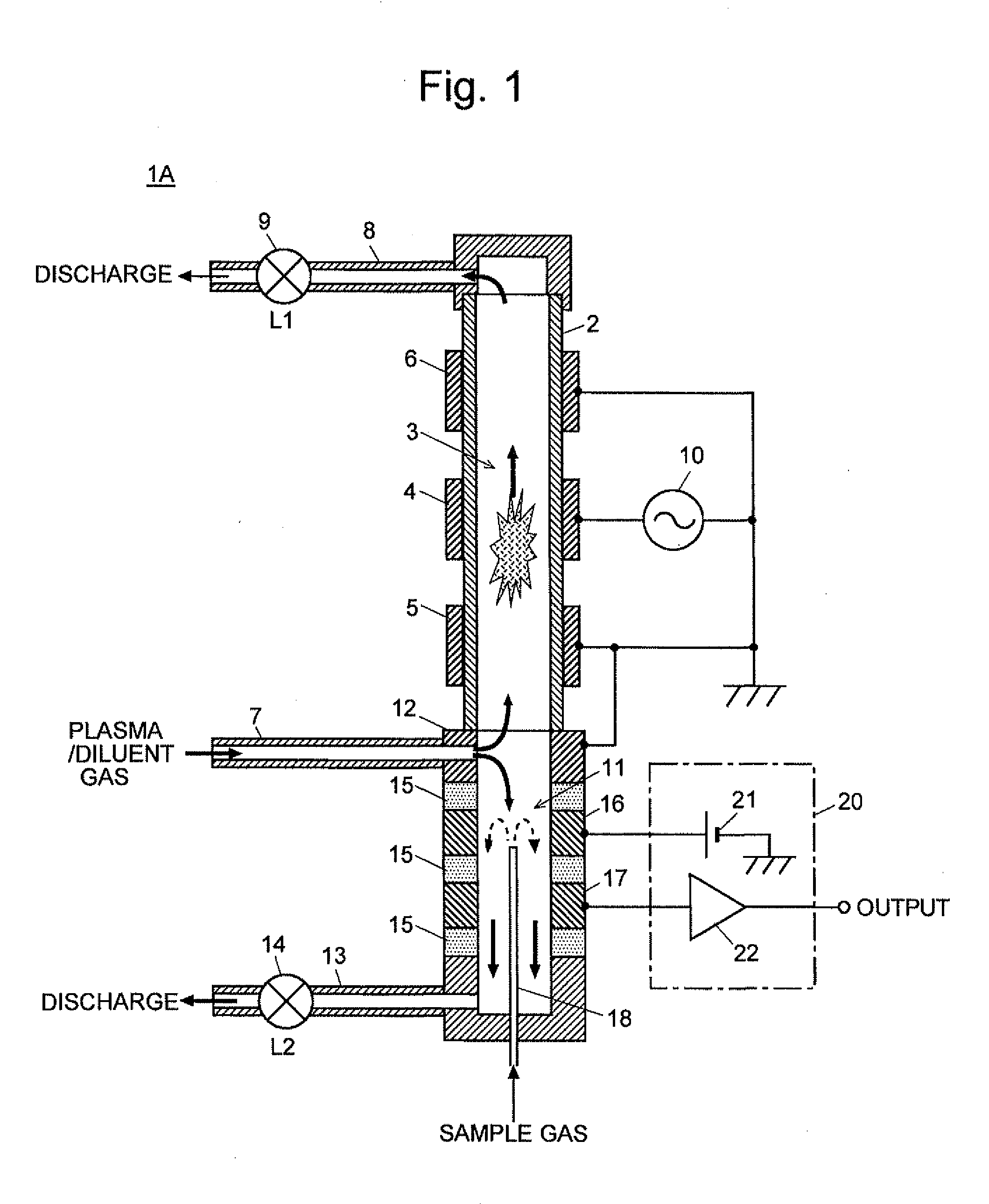
[0042]A discharge ionization current detector according to one embodiment (first embodiment) of the present invention is hereinafter described with reference to FIG. 1. FIG. 1 is a schematic configuration diagram of the discharge ionization current detector according to the first embodiment.

[0043]The discharge ionization current detector 1A of the present embodiment includes a cylindrical tube 2 made of a dielectric material, such as quartz. The inner space of this tube 2 is the first gas passage 3. For example, the cylindrical tube 2 may be a quartz tube having an outer diameter of 3.9 mm. Ring-shaped plasma generation electrodes 4, 5 and 6, which are made of a metal (e.g. stainless steel or copper), are circumferentially provided at predetermined intervals on the outer wall surface of the cylindrical tube 2. According to this design, the dielectric wall of the cylindrical tube 2 between the first gas passage 3 and the plasma generation electrodes 4, 5 and 6 functions as a dielectr...

second embodiment

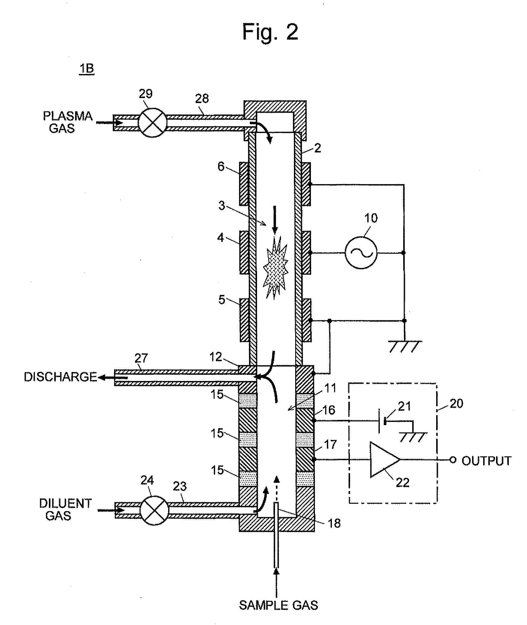
[0054]FIG. 2 is a schematic configuration diagram of a discharge ionization current detector 113 according to the second embodiment of the present invention. The same components as used in the first embodiment are denoted by the same numerals, and hence no detailed explanation will be made for these components. It should be noted that the components corresponding to the gas supply pipe 7, the first gas discharge pipe 8, the first flow controller 9, the second gas discharge pipe 13 and the second flow controller 14 in the first embodiment are structurally identical to these components and yet denoted by different numerals since they have different functions. That is to say, in the discharge ionization current detector of the second embodiment, a plasma gas is supplied into the first gas passage 3 through a plasma-gas supply pipe 28 connected to the upper end of the cylindrical tube 2, and a diluent gas is supplied into the second gas passage 11 through a diluent-gas supply pipe 23 co...

third embodiment

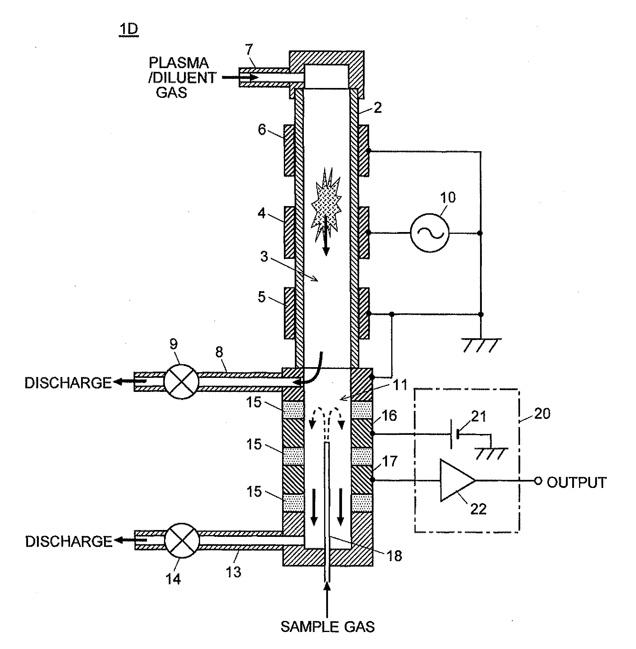
[0057]As already stated, although the detectors of the first and second embodiments have almost the same basic configuration, they have a significant difference in terms of the suitable sample-concentration range. That is to say, the first embodiment is suitable for the high-sensitivity detection of low-concentration samples but not for the detection of high-concentration samples. By contrast, the second embodiment, which is suitable for the detection of high-concentration samples, is inferior to the first embodiment in detection sensitivity since it requires the supply of a certain amount of diluent gas to create a smooth flow of gas through the second gas passage 11. To address this problem, the detector according to the third embodiment of the present invention has a mechanism for appropriately switching the passage configuration between the first embodiment and the second embodiment so as to cover a wide range of sample concentration.

[0058]FIG. 3 is a schematic configuration dia...


PUM

PropertyMeasurementUnit
frequencyaaaaaaaaaa
outer diameteraaaaaaaaaa
frequencyaaaaaaaaaa

Abstract

A discharge ionization current detector capable of supplying plasma gas in large quantity to stabilize plasma simultaneously with lowering the sample dilution ratio to improve detection sensitivity is provided. A gas supply pipe 7 for supplying a plasma gas, which also functions as a dilution gas, is connected to a point near the connecting section of a first gas passage 3 having electrodes 4-6 for plasma generation and a second gas passage having electrodes 16 and 17 for ion detection. A first gas discharge pipe 8 is connected to the other end of the first gas passage 3, and a second gas discharge pipe 13 is connected to the other end of the second gas passage 11. Flow controllers 9 and 14 are provided in the gas discharge pipes 8 and 13, respectively. The flow rate of the gas passing through a plasma generation area and that of the gas passing through an ion current detection area can be independently regulated. Therefore, for example, it is possible to increase the former flow rate to stabilize the plasma and simultaneously decrease the latter flow rate to enhance the detection sensitivity for a low-concentration sample.

Description

[0001]The present invention relates to a discharge ionization current detector primarily suitable as a detector for a gas chromatograph (GC), and more specifically to a discharge ionization current detector using a low-frequency barrier discharge.BACKGROUND OF THE INVENTION[0002]As the detector for a gas chromatograph, various types of detectors have conventionally been proposed and practically applied, such as a thermal conductivity detector (TCD), electron capture detector (ECD), flame ionization detector (FID), flame photometric detector (FPD) and flame thermionic detector (FTD). Among those detectors, the FID is most widely used, particularly for the purpose of detecting organic substances. The FID is a device that ionizes sample components in a sample gas by hydrogen flame and detects the resultant ion current. It can attain a wide dynamic range of approximately six orders of magnitude. However, the FID has the following drawbacks: (1) Its ionization efficiency is low, so that ...

Claims


Application Information

Patent Timeline
Patent Type & Authority Applications(United States)
IPC IPC(8): G01N27/70
CPCG01N27/70G01N27/68G01N27/62G01N30/64G01N2030/642
Inventor SHINADA, KEIHORIIKE, SHIGEYOSHINISHIMOTO, TAKAHIRO
Owner SHIMADZU CORP
Why Eureka
Try Eureka