Fluidized bed gasifier with solids discharge and classification device

a gasifier and flue gas technology, applied in the direction of gasifier mechanical details, furnaces, lighting and heating apparatus, etc., can solve the problems of high erosion of mechanical parts of discharge devices, complex mechanical design, mechanical feeder operation, maintenance and replacement, etc., to achieve sufficient downward momentum, increase overall conversion of feed materials, and prolong the effect of residence tim

Inactive Publication Date: 2011-08-04
SYNTHESIS ENERGY SYST
View PDF11 Cites 22 Cited by
  • Summary
  • Abstract
  • Description
  • Claims
  • Application Information

AI Technical Summary

Benefits of technology

[0011]By separating the heavier and larger solids residues from smaller and lighter solids residues, gas and solids reaction is carried out more thoroughly, and higher overall conversions of feed materials are achieved. It is known that as the gasification reactions of carbonaceous feed solids progress, more fully reacted solids become larger or heavier depending on the type of feed materials. The present invention together with the classifier selectively discharge the more fully reacted larger or heavier solids residues from the fluidized bed gasifier, and return the less reacted, smaller or lighter solids to the fluidized bed gasifier, and allow the less reacted solids to have a longer residence time required for more complete gasification reactions.
[0012]The present invention further improves overall conversion rate by providing feed gas beneath the classifier. Solids discharged from the venturi throat enter the classifier immediately below the venturi and further react with the up-flowing feed gases.
[0013]The present invention also provides a removable venturi design where the eroded venturi can be readily replaced with a spare venturi device thereby shortening the down time and improve the overall availability of the gasifier. As discussed above, the venturi throat is under constant bombardment of high velocity gas and solids streams at high temperature and high pressure, and is subjected to high erosion and requires frequent repairs or replacements causing prolonged shutdowns of the gasifier system.
[0014]The present invention further provides an improved apparatus and method to distribute feed gases for fluidized bed gasifier. More specifically, a conically shaped perforated distribution plate or grid is equipped with multiple horizontally- or downwardly-oriented openings or grid holes through which the feed gases flow and enter the fluidized bed. The distribution plate has a cone angle, and the grid holes are sized and spaced, so as to provide a more uniform distribution of feed gases, improved solids circulation pattern, and better gas-solids mixing in the fluidized bed gasifier. In a preferred embodiment, the entrances of the grid holes are placed below the distribution plate, and are covered with certain metal attachments to prevent solids from flowing into the grid holes and falling into the plenum below the distribution plate causing undesired combustion reactions.

Problems solved by technology

Conventional underflow discharge systems for fluidized bed gasifiers operated at high temperatures and pressures using control valves or mechanical feeders frequently result in erratic solids flow rate and high erosions to mechanical parts of discharge devices.
The mechanical design, construction and operation of control valve and mechanical feeder are complex and require frequent repairs and replacements.
The conventional discharge system often results in unscheduled shutdowns and affects the performance and reliability of the gasifier system.
As a consequence, the venturi tube is subjected to high erosion and requires frequent and expensive repairs or replacements, which result in frequent or prolonged shutdowns.
Solids in fluidized bed, however, commonly migrate through the openings of the distribution plate and fall into the plenum under the distribution plate causing adverse problems such as combustion in the plenum.

Method used


Image

  • Fluidized bed gasifier with solids discharge and classification device
  • Fluidized bed gasifier with solids discharge and classification device
  • Fluidized bed gasifier with solids discharge and classification device

Examples


Embodiment Construction

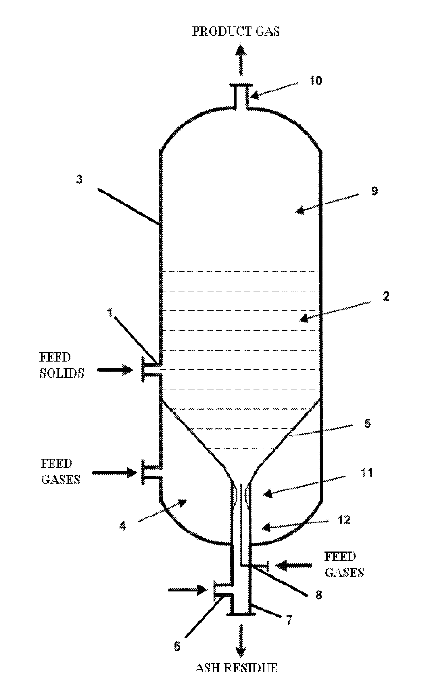
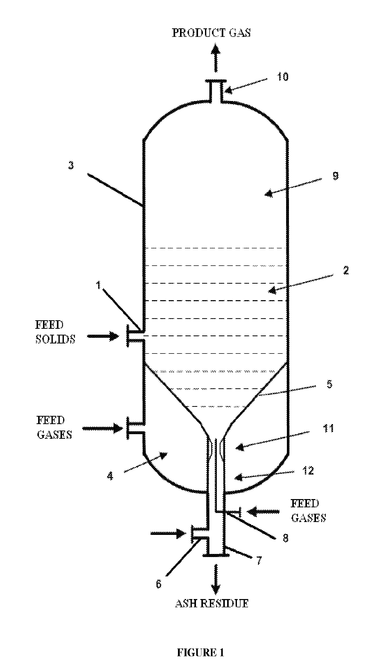
[0021]Referring to the figures, the various aspects of the present invention are described in more detail below. FIG. 1 provides a schematic diagram of one embodiment of a fluidized bed gasifier according to the present invention. The fluidized bed gasifier comprises an integrated solids residue discharge and classification device. Solids feed comprising crushed carbonaceous fuels such as coal or biomass is pneumatically or mechanically fed through a feed pipe 1 to the fluidized bed 2 of the gasifier 3. Gaseous feed containing a mixture of steam and oxidant, such as air or oxygen, is injected to the gasifier at three locations: 1) the “grid gas” is injected to the plenum 4 below the distribution grid 5, 2) the “classifier gas” is injected through a connection pipe 6 to the ash discharge line 7, and 3) the “jet gas” is injected through a center jet pipe 8.

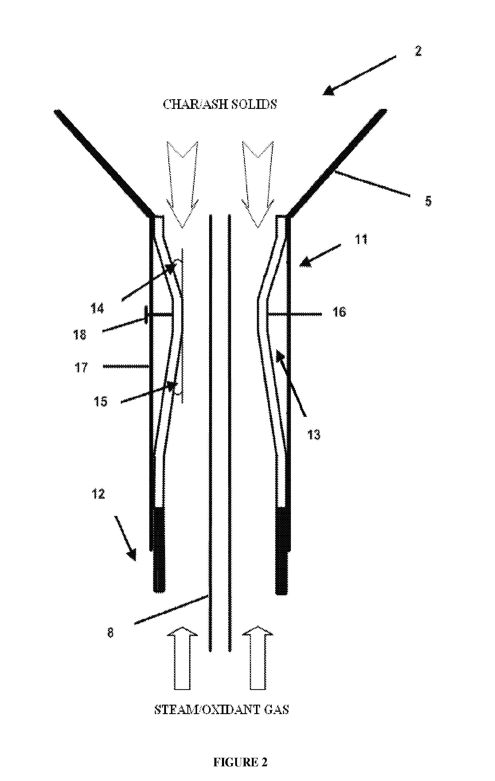
[0022]The solids feed is reacted with the gaseous feed in the fluidized bed 2 controlled at a specific temperature, pressure and r...


PUM


Abstract

An apparatus for withdrawing solids from a fluidized bed reactor comprises a venturi tube connected to the stem end of a funnel-shaped distribution plate, and a center jet pipe enclosed within the venturi, wherein a jet stream of feed gas is delivered above the venturi throat. Preferably, the distribution plate is equipped with multiple horizontally- or downwardly-oriented grid holes through which the feed gases flow and enter the fluidized bed, which holes may be covered by metal plates to prevent solids from weeping through grid holes and falling into the plenum below the distribution plate. The venturi is preferably engineered to be readily removable from the rest of the gasifier reactor for repair or replacement. Also provided is a fluidized bed reactor comprising the above apparatus.

Description

FIELD OF THE INVENTION[0001]The present invention relates to methods and apparatuses of distributing feed gas to a fluidized bed reactor and discharging solids residues therefrom.BACKGROUND OF THE INVENTION[0002]Solids residues generated from fluidized bed gasifiers operated at high temperatures and pressures need to be discharged from the gasifiers in a controllable and steady manner to maintain adequate bed height and solids residence time required for gasification reactions. Conventional underflow discharge systems for fluidized bed gasifiers operated at high temperatures and pressures using control valves or mechanical feeders frequently result in erratic solids flow rate and high erosions to mechanical parts of discharge devices. The mechanical design, construction and operation of control valve and mechanical feeder are complex and require frequent repairs and replacements. The conventional discharge system often results in unscheduled shutdowns and affects the performance and...

Claims


Application Information

Patent Timeline
Patent Type & Authority Applications(United States)
IPC IPC(8): B01J8/18B01J8/00
CPCB01J8/003B01J8/1818B01J8/44B01J2208/00761B01J2208/00778C10J2300/0973C10J2200/09C10J2200/15C10J2300/0916C10J2300/093C10J2300/0956C10J3/523
Inventor SHENG, TSUNG-YAO ROBERT
Owner SYNTHESIS ENERGY SYST
Why Eureka
Try Eureka