Method of fabrication visible light absorbed TiO2/CNT photocatalysts and photocatalytic filters

a technology of visible light absorbed tio2/cnt photocatalyst and photocatalyst filter, which is applied in the direction of liquid gas reaction of thin film type, physical/chemical process catalyst, gas-gas reaction process, etc., can solve the problem that the photocatalyst titanium dioxide film provided therein cannot operate without the illumination of uv lights, and the application of photocatalysts is quite limited, so as to achieve the effect of improving the photoca

Inactive Publication Date: 2011-08-11
NATIONAL TSING HUA UNIVERSITY
View PDF9 Cites 26 Cited by
  • Summary
  • Abstract
  • Description
  • Claims
  • Application Information

AI Technical Summary

Benefits of technology

[0020]The photocatalytic filter of the present invention is a visible light absorbed photocatalysts filter that can be workable with visible light and therefore can be applied into various uses such as the filtering net of an air conditioner without the limitation of the using of UV light sources. That is, there is no need to install UV light source equipment to provide artificial UV lights for the photocatalysts filter. In contrast, a traditional photocatalyst filter cannot work if the UV light exposure is absent, the photocatalyst of the traditional filters may lose its photocatalysis feature if no UV light is provided and therefore is limited to the place where it is used.
[0021]In the prior arts, a photocatalysts filter is made...

Problems solved by technology

Therefore, if a conventional photocatalyst titanium dioxide film is illuminated with visible light (with wavelength of longer than 400 nm), free radicals cannot be generated since only with the exposure to UV lights can the conventional photocatalyst be excited to an excited state.
However, the photocatalysts titanium dioxide film provided thereof still cannot operate without the illumination of UV lights, whereby the application of the photocatalysts is quite limited to the environment having nat...

Method used


Image

  • Method of fabrication visible light absorbed TiO2/CNT photocatalysts and photocatalytic filters
  • Method of fabrication visible light absorbed TiO2/CNT photocatalysts and photocatalytic filters
  • Method of fabrication visible light absorbed TiO2/CNT photocatalysts and photocatalytic filters

Examples


example 1

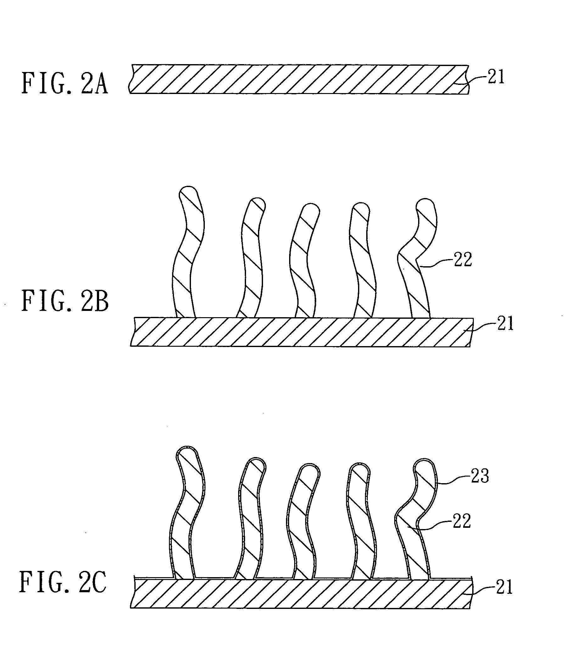
[0033]Reference with FIGS. 2A-2C, a process flow chart of fabricating a visible light absorbed TiO2 / CNT photocatalysts is shown. First, (a) a substrate 21 is provided as shown in FIG. 2A, wherein a silicon-based substrate is used. Then, (b) a plurality of carbon nanotubes 22 is formed on the substrate 21 by a CVD method, as shown in FIG. 2B. After that, (c) a titanium source and an oxygen source (not shown) are provided, and (d) by using an atomic deposition method, with conditions of 150° C. of temperature, 1 mbar of pressure, and a nitrogen atmosphere, the titanium source and the oxygen source are reacted to form a titanium dioxide layer 23 on the carbon nanotubes 22. Then, the above step (d) is repeated for 800 times to increase the thickness of the titanium dioxide layer 23. Subsequently, (d1) an annealing process is performed on the carbon nanotubes 22 coated with the titanium dioxide layer 23 (not shown). Therefore, a visible light absorbed photocatalysts comprising a substrat...

example 2

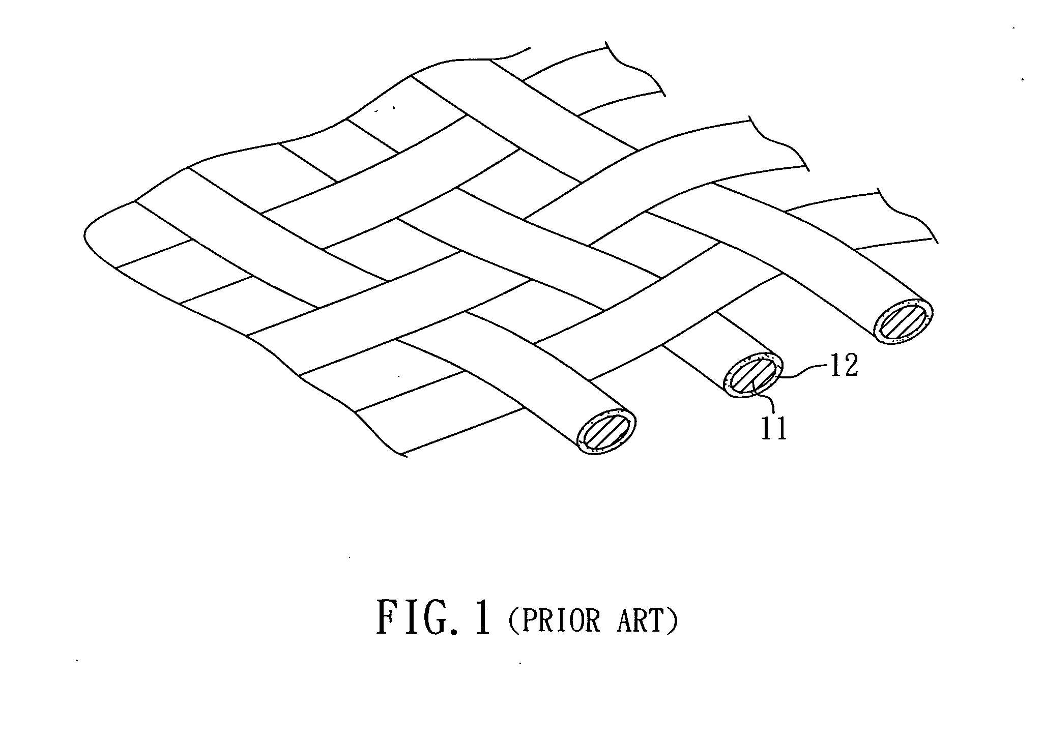
[0035]The same method as described in the example 1 is used except that a carbon fiber cloth is used as the substrate 21 to replace the silicon-based substrate.

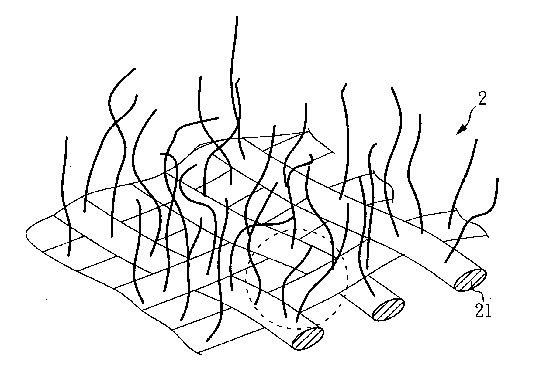
[0036]Reference with FIGS. 3 and 4, a schematic view and a cross section view of a photocatalysts filter of the present example are shown, in which FIG. 4 is the enlarged view of the cycled part shown in the FIG. 3. The photocatalysts filter of the present example comprises a substrate 21 (i.e. the carbon fiber cloth), a plurality of carbon nanotubes 22, and a titanium dioxide layer 23. The carbon nanotubes 22 form on the surface of the substrate 21, ends 221 of the carbon nanotubes 22 connect to the surface of the substrate 21, and the titanium dioxide layer 23 covers the surface of the carbon nanotubes 22 formed on the substrate 21. The length of the carbon nanotubes 22 is about 300 μm.

[0037]According to the photocatalysts filter 2 of the present example, the titanium dioxide layer 23 is formed covering the carbon nanotubes...

example 3

[0040]Reference with FIGS. 5A-5D, a process flow chart of fabricating a visible light absorbed TiO2 / CNT photocatalysts is shown. First, (a) a silicon-based substrate 24 is provided as shown in FIG. 5A. Then, (b) a plurality of carbon nanotubes 22 is formed on the substrate 24 by a CVD method, as shown in FIG. 5B. After that, (c) a titanium source and an oxygen source (not shown) are provided, and (d) by using an atomic deposition method, with conditions of 150° C. of temperature, 1.5 mbar of pressure, and at a nitrogen atmosphere, the titanium source and the oxygen source are reacted to form a titanium dioxide layer 23 on the carbon nanotubes 22. Then, the above step (d) is repeated for 800 times to increase the thickness of the titanium dioxide layer 23. Subsequently, (d1) an annealing process is performed on the carbon nanotubes 22 coated with the titanium dioxide layer 23 (not shown). Finally, the silicon-based substrate 24 is removed to obtain the photocatalysts of the present e...


PUM

PropertyMeasurementUnit
Lengthaaaaaaaaaa
Thicknessaaaaaaaaaa
Efficiencyaaaaaaaaaa

Abstract

A method of fabricating visible light absorbed TiO2/CNT photocatalysts and photocatalytic filters is disclosed, in which the method of fabricating the photocatalysts comprises steps: (a) providing a substrate; (b) forming a plurality of carbon nanotubes on the substrate; (c) providing a titanium source and an oxygen source; and (d) forming at least one titanium dioxide layer on the carbon nanotubes. The filter of the present invention comprises: a substrate, a plurality of carbon nanotubes, and a titanium dioxide layer. The plurality of carbon nanotubes form on the surface of the substrate, one end of each carbon nanotube connects to the substrate, and the titanium dioxide layer covers the surface of the carbon nanotubes. The filter of the present invention is a visible light absorbed filtering net, the titanium dioxide layer formed on the CNTs has high uniformity and therefore the photodegradation efficiency of the filter is an improvement.

Description

BACKGROUND OF THE INVENTION[0001]1. Field of the Invention[0002]The present invention relates to method of fabricating TiO2 / CNT photocatalysts and a photocatalytic filter provided by the same and, more particularly, to a method of fabricating visible light absorbed TiO2 / CNT photocatalysts and a photocatalytic filter provided by the same.[0003]2. Description of Related Art[0004]A photocatalyst is a material that can provide various functions such as sterilization, deodorization, and cleaning by the free radicals thereof being generated after exposure to light. Many materials have been taken as the photocatalyst material, and among them titanium dioxide is the mostly used one. In the prior arts, a titanium dioxide film is usually formed by using a sol-gel method, but the provided photocatalyst titanium dioxide film can work (be able to generate free radicals) only under the exposure to UV lights. Therefore, if a conventional photocatalyst titanium dioxide film is illuminated with visi...

Claims


Application Information

Patent Timeline
IPC IPC(8): B01J21/18B01J21/06B01J35/02
CPCB01J21/063B01J21/185B01J35/004B82Y30/00B01J37/0215B01J37/0238B01J35/06
Inventor HSU, WEN-KUANGKUO, HSIN-FULU, SHEN-YITANG, CHIUNG-WENLIN, YU-HSIEN
Owner NATIONAL TSING HUA UNIVERSITY
Why Eureka
Try Eureka