Heat-Dissipating Device For Supplying Cold Airflow

a heat-dissipating device and thermoelectric cooling chip technology, which is applied in indirect heat exchangers, lighting and heating apparatus, and semiconductor/solid-state device details, etc., can solve the problems of reducing the cold-generating capacity, rusting the electronic elements of the heat-dissipating device, and the low temperature of the thermoelectric cooling chip at the end of the shelf. achieve the effect of convenient use and better practicability

Inactive Publication Date: 2011-08-18
GOLDEN SUN NEWS TECHN +1
View PDF3 Cites 25 Cited by
  • Summary
  • Abstract
  • Description
  • Claims
  • Application Information

AI Technical Summary

Benefits of technology

[0010]In comparison with prior art, according to the heat-dissipating device for supplying cold airflow of the present invention, the cold-end surface of the thermoelectric cooling chip is abutted by the cold-airflow supplying module comprising the super heat pipe, the fan and the fins assembly. The super heat pipe rapidly conducts the cold generated by the cold-end surface of the thermoelectric cooling chip to the fins assembly. Then, the cold is uniformly conducted to the respective fins by means of the large surface area of the fins assembly

Problems solved by technology

However, since the temperature of the cold-end surface of the thermoelectric cooling chip is extremely low, frost will be generated on the cold-end surface to reduce the cold-generating capacity if the cold is not conducted to other places immediately.
On the other hand, when the thermoelectric cool

Method used


Image

  • Heat-Dissipating Device For Supplying Cold Airflow
  • Heat-Dissipating Device For Supplying Cold Airflow
  • Heat-Dissipating Device For Supplying Cold Airflow

Examples


Embodiment Construction

[0019]The characteristics and technical contents of the present invention will be described with reference to the accompanying drawings. However, the drawings are illustrative only, but not used to limit the present invention.

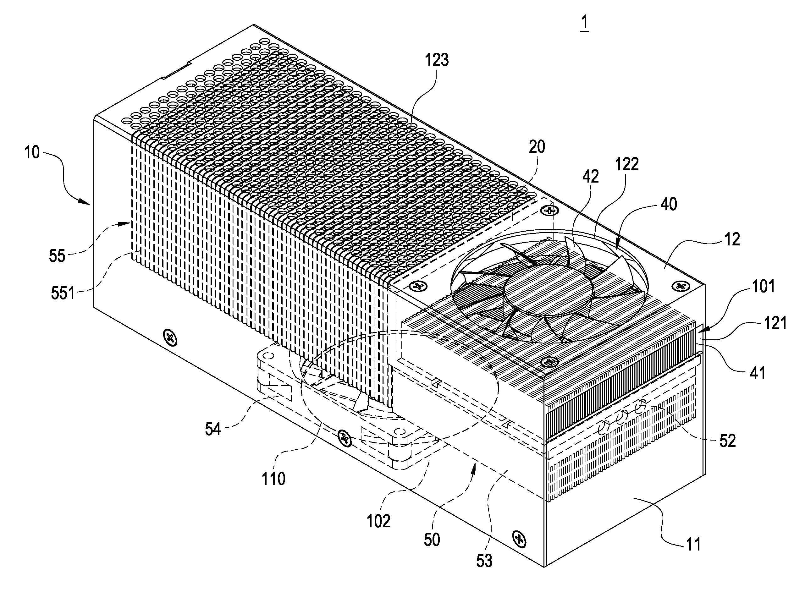
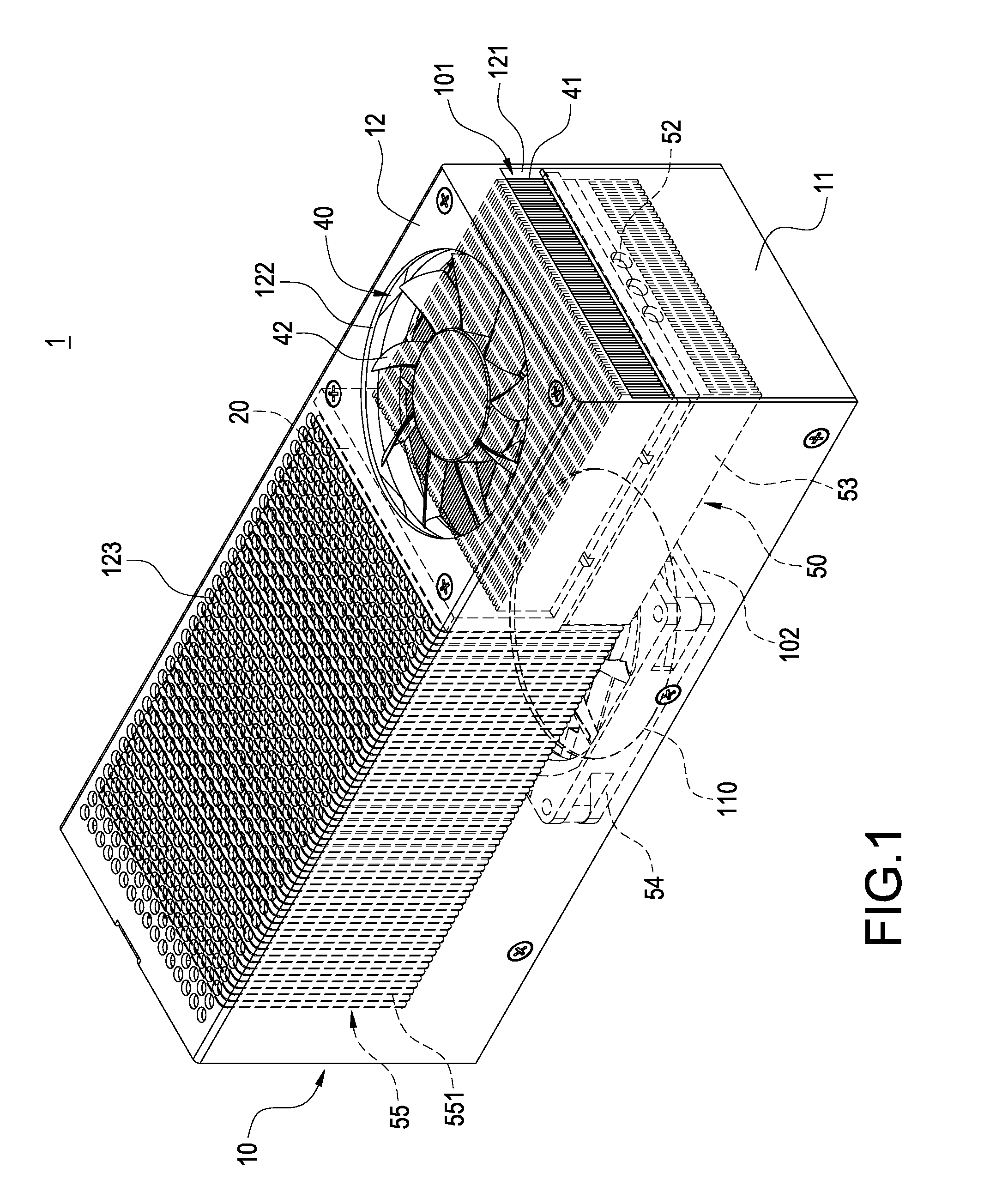
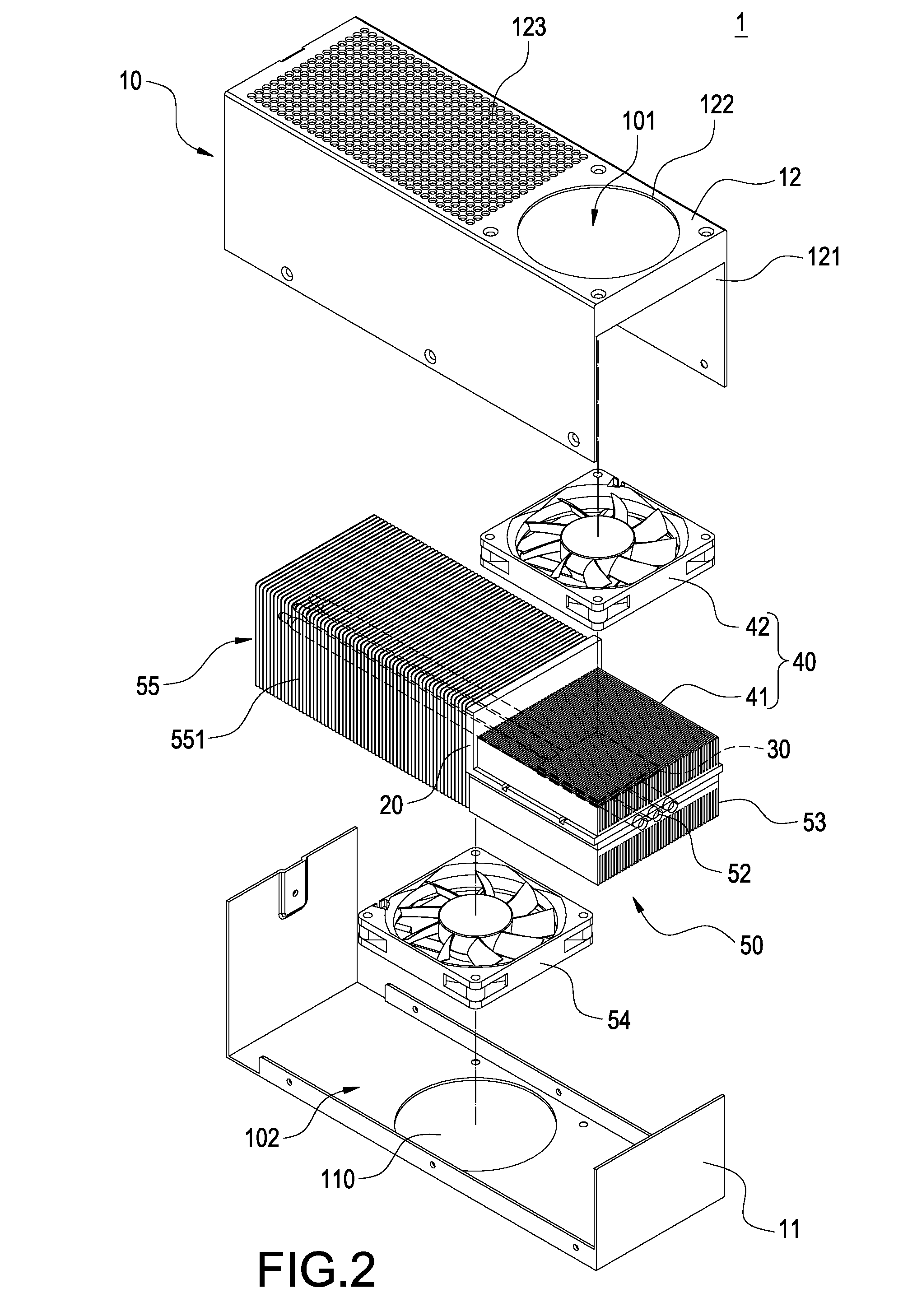
[0020]Please refer to FIGS. 1 and 4. FIG. 1 is a perspective view showing the external appearance of the present invention, FIG. 2 is an exploded perspective view (I) of the present invention, FIG. 3 is an exploded perspective view (II) of the present invention, and FIG. 4 is an assembled cross-sectional view of the present invention. The present invention provides a heat-dissipating device for supplying cold airflow, which includes a casing 10, a thermal insulation plate 20, a thermoelectric cooling chip 30, a heat-dissipating module 40, and a cold-airflow supplying module 50.

[0021]The casing 10 is constituted of a base 11 and an upper cover 12. The base 11 is provided with a cold air outlet 110. The upper cover 12 is provided with a hot air outlet 121, a firs...


PUM


Abstract

A heat-dissipating device (1) includes a casing (10) and a thermal insulation plate (20) provided within the casing (10). The thermal insulating plate (20) divides the interior of the casing (10) into a first accommodating space (101) and a second accommodating space (102). A hot air outlet (121) and a first air inlet (122) of the casing (10) are in communication with the first accommodating space (101). A cold air outlet (110) and a second air inlet (123) of the casing (10) are in communication with the second accommodating space (102). A thermoelectric cooling chip (30) is disposed in a through-hole (200) of the thermal insulation plate (20) and has a hot-end surface (31) facing the first accommodating space (101) and a cold-end surface (32) facing the second accommodating space (102). A heat-dissipating module (40) is received in the first accommodating space (101). A cold-airflow supplying module (50) is received in the second accommodating space (102). The heat generated by the hot-end surface (31) is dissipated to the hot air outlet (121) by the thermal conduction of the heat-dissipating module (40). The cold generated by the cold-end surface (32) is conducted and distributed uniformly by the cold-airflow supplying module (50) to the cold air outlet (110).

Description

BACKGROUND OF THE INVENTION[0001]1. Field of the Invention[0002]The present invention relates to a heat-dissipating device, and in particular to a heat-dissipating device having a thermoelectric cooling chip.[0003]2. Description of Prior Art[0004]Traditionally, a heat-dissipating device used in a high-power central processing unit includes: a heat sink directly mounted on the central processing unit, heat-dissipating fins provided above the central processing unit, heat pipes combined with the heat-dissipating fins, and a fan. The heat of the central processing unit is conducted to the heat pipes and the heat-dissipating fins. Finally, the fan generates airflow to dissipate the heat outside the computer.[0005]With the increase of the operating speed of the central processing unit, the mount of heat generated by the central processing unit also raises to a much larger extent. Thus, it is necessary to develop a heat sink with increased heat-dissipating efficiency. Many manufacturers u...

Claims


Application Information

Patent Timeline
IPC IPC(8): F25B21/02F28D15/00F28F1/20
CPCF25B21/02F25B2321/0251H01L23/3675H01L23/38H01L23/427H01L2924/0002H01L23/467H01L2924/00
Inventor CHENG, CHIH-HUNGHSU, KENLIN, CHEN-HSIANGLIN, KUO-LEN
Owner GOLDEN SUN NEWS TECHN
Why Eureka
Try Eureka