Downhole device

a drilling device and downhole technology, applied in the field of drilling downhole devices, can solve the problems of affecting affecting the efficiency of drilling process, and little success in creating a panacea for stick-slip or the success of diminishing the harmonics of drill string, so as to achieve the effect of ensuring the efficiency and effectiveness of drilling process

Inactive Publication Date: 2011-08-18
SWIETLIK GEORGE +1
View PDF29 Cites 70 Cited by
  • Summary
  • Abstract
  • Description
  • Claims
  • Application Information

AI Technical Summary

Benefits of technology

[0090]This integrated and adaptive approach allows for continuous adjustment of the damping capabilities and characteristics of the instant device in response to changes in drilling conditions. The ability, conferred by downlink protocol, of an instrumented version of the instant device to comprehend alterations to proximal drilling harmonics is perceived as an improvement over prior art. The characteristics may be derived from a variety of sensors and instruments located either within the drilling assembly or at the surface of the earth.
[0091]Thus the versatility of the damping system and method increases, creating the ability to adapt to changing drilling conditions in real time without compromising the efficiency and effectiveness of the drilling process.

Problems solved by technology

For example, variations in the torque applied to the drill string will result in a torsional vibration in the drill string.
. . probably due to unevenness of formation strength, random breakage of rock and amplification of these effects by mode coupling .
Prior art in the domain of vibration measurement and control is plentiful, yet, to date, there has been little success in creating a panacea for stick-slip or success in diminishing drillstring harmonics and thereby deriving improvements to the drilling process.
Thus variations in bit generated torque will reflect in drillstring torque which feeds back into the rotary drive system: the system is complex, iterative and chaotically changing.
These devices have some degree of effectiveness, but are constrained by having their own internal natural frequency, which, at some stage will compound the existing wellbore harmonic.
Additionally, shock subs are, largely, incompatible with directional drilling processes, directional wells and also relatively ineffective when dealing with high magnitude harmonic vibrations.
These devices also have inherent natural frequencies of their own which are not field tuneable to provide wider ranges of damping capability.
Downhole sampling and processor speeds in earlier devices precluded analysis across the wider range of harmonics.
A recent study has shown that these equations, even when modified to account for fluid added mass and precessional forces, do not accurately predict critical rotating speeds and do not correspond well with field experience.”
Presently no generally accepted method exists to accurately predict critical rotary speeds.”
However, Jogi (U.S. Pat. No. 6,205,851) METHOD FOR DETERMINING DRILL COLLAR WHIRL IN A BHA AND METHOD FOR DETERMINING BOREHOLE SIZE identified the inherent weaknesses in these modelling efforts, noting that even slight variations in hole enlargement or in drill-collar concentricity caused by bends within the drill-collar, or drill-collar “sag”, curvature of the borehole or BHA imbalances reduces pre-well BHA modelling effectiveness as it alters the natural frequency of the BHA.
Unfortunately these variations are unquantifiable until the well is in progress.
Research has shown that the main causes of premature bit and BHA damage in any one drilling scenario are, largely, confined to one or two major frequencies with single “sidebands”.
Using these methods may reduce harmonic vibration, yet compromise rate of penetration as a result of the selection of sub-optimal drilling RPM ranges.
The Forrest device is non instrumented and non-adaptive.
Drillstring overfeed causes the over-torsion and severe twisting of the drillstring.
Despite the use of a “controllable” MR damping element, the experiments which were carried out and reported in Raymond showed that some spring configurations were less beneficial than others:
However, the inference should not be made, nor does the patent documentation confirm that this particular frequency is particularly significant.
The turbine generator adds significant additional length to the device.
Unfortunately, not all of these inputs can be measured in the downhole environment.
Without information pertaining to surface conditions and more specifically to surface RPM, the downhole device may have insufficient information to be able to determine if the distal drilling environment requires adjustment or is within acceptable limits.
All prior art downlink protocols have in some way compromised the integrity of drilling operations.
Additionally, the inventors believe that the partial successes of prior art and the body of information accumulated to date indicate that it is insufficient to focus on a single source of harmonic drilling problems to resolve a solution, and that an integrated closed loop and in addition, adaptive approach may be required in some circumstances.

Method used


Image

  • Downhole device
  • Downhole device
  • Downhole device

Examples


second embodiment

OF THE INVENTION

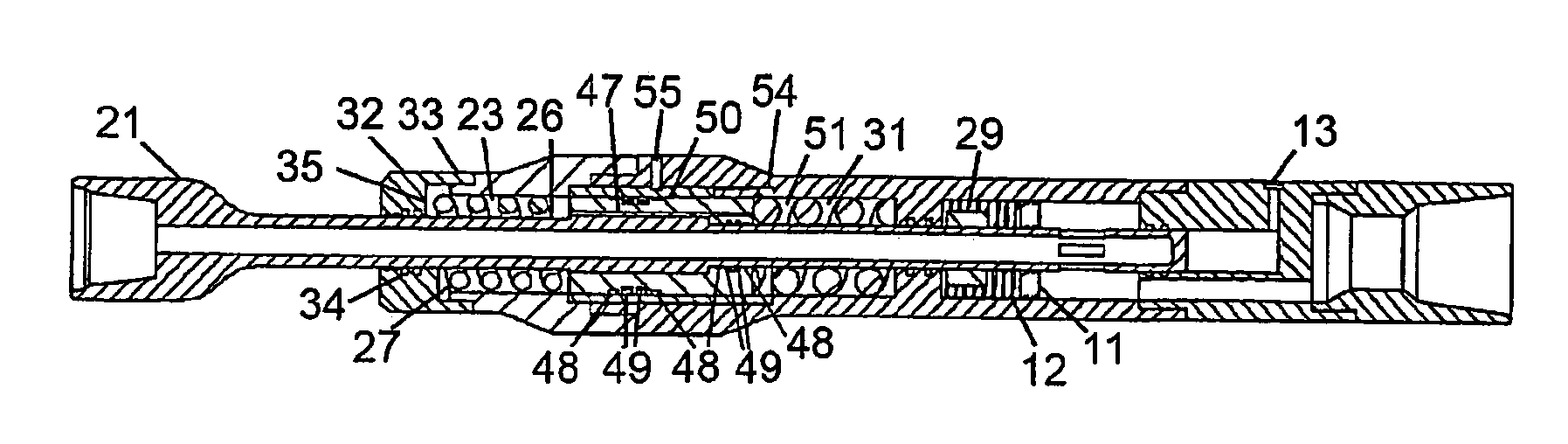
[0187]In both these methods, the modified sleeve assembly [50] is constructed from non-magnetic or magnetically transparent material and is equipped with seals [48], [49], which hermetically seal the volumes between the upper, proximal, chamber [31] and lower, distal, chamber [23]. In this configuration the sleeve acts as a toroidally configured piston means equipped with fluid bypass means [47]. The emplacement and distribution of seals along the length of the tool can be used to form different arrays and arrangements of interconnected fluid chambers for the purpose of controlling fluid movement and transfer across two or more relevant chambers. In this instance the combination of seals at the extremities of each of the chambers combine to form a proximate reservoir chamber [31] and a distal reservoir chamber [23] containing magneto-rheological fluid [51] therein. The reservoir chambers are connected by fluid choke ports [47] which are preferentially contained withi...

third embodiment

OF THE INVENTION

[0193]Proportional Damping Strokes

[0194]As may be inferred from the description of the previous embodiment, electro magnetic coils [53] may be substituted for rare-earth magnets [52]. Although their installation represents an overall increase in system complexity, the presence of instrumentation controlled electronic systems [10] equipped with clock timing capability allows for more precise application of timed, variable control voltages to the magnetorheological fluids [51] in conjunction with advantageous phase shifting of damping capability. In summary, the EM Coil configuration of the instant device illustrated in FIG. 13 allows greater control over the MR fluid [51] elements of the design.

[0195]Substitution of EM coils [53] as means for controlling the MR Fluid [51] requires the addition of control instrumentation [10]. The instrumented device may be preferentially equipped with sensors [not illustrated] which provide measurements of shock, acceleration and freq...


PUM


Abstract

A downhole device comprising a mandrel (21) suitable for connection to a drilling assembly (3), a housing (22) surrounding said mandrel said housing being suitable for connection to the alternate end of a drilling assembly and a compensating mechanism (25) configured to adjust an axial force applied to said mandrel by changing the relative position of the mandrel with respect to the housing.

Description

TECHNICAL FIELD[0001]The present invention relates to oil and gas drilling and more specifically to a method, system and apparatus for reducing shock and drilling harmonic vibration within the rotary drilling assembly.BACKGROUND[0002]The invention is designed to work cooperatively with commonly utilized components of drilling assemblies. Components commonly in use in the drilling assembly are selected for specific properties. Drill collars, for example, are selected for their ability to convey weight and torque to the bit. Accordingly, they are torsionally rigid, relatively inflexible and are able to be run in compression without detriment. Drill-pipe, by comparison, is less torsionally rigid and has a much lower weight per unit length and is designed to be used in tension. In areas where high levels of drillstring vibration are encountered drillstring component failure is frequently found in the environs of the intersection of drill-collars and drill-pipe.[0003]Acknowledging the pr...

Claims


Application Information

Patent Timeline
Patent Type & Authority Applications(United States)
IPC IPC(8): E21B17/07E21B7/24
CPCE21B17/073E21B17/07
Inventor SWIETLIK, GEORGEMCLOUGHLIN, STEPHEN JOHN
Owner SWIETLIK GEORGE
Why Eureka
Try Eureka