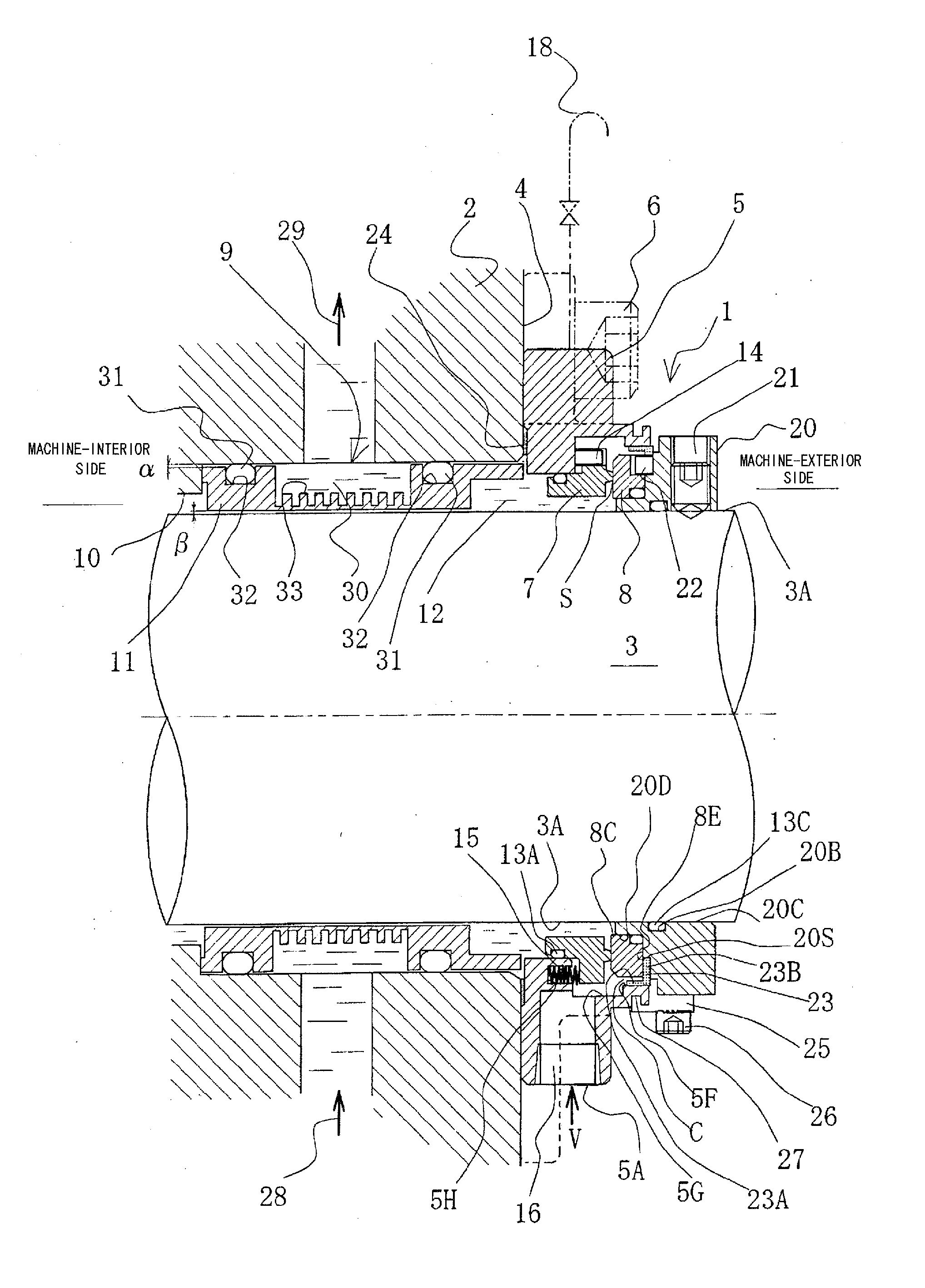
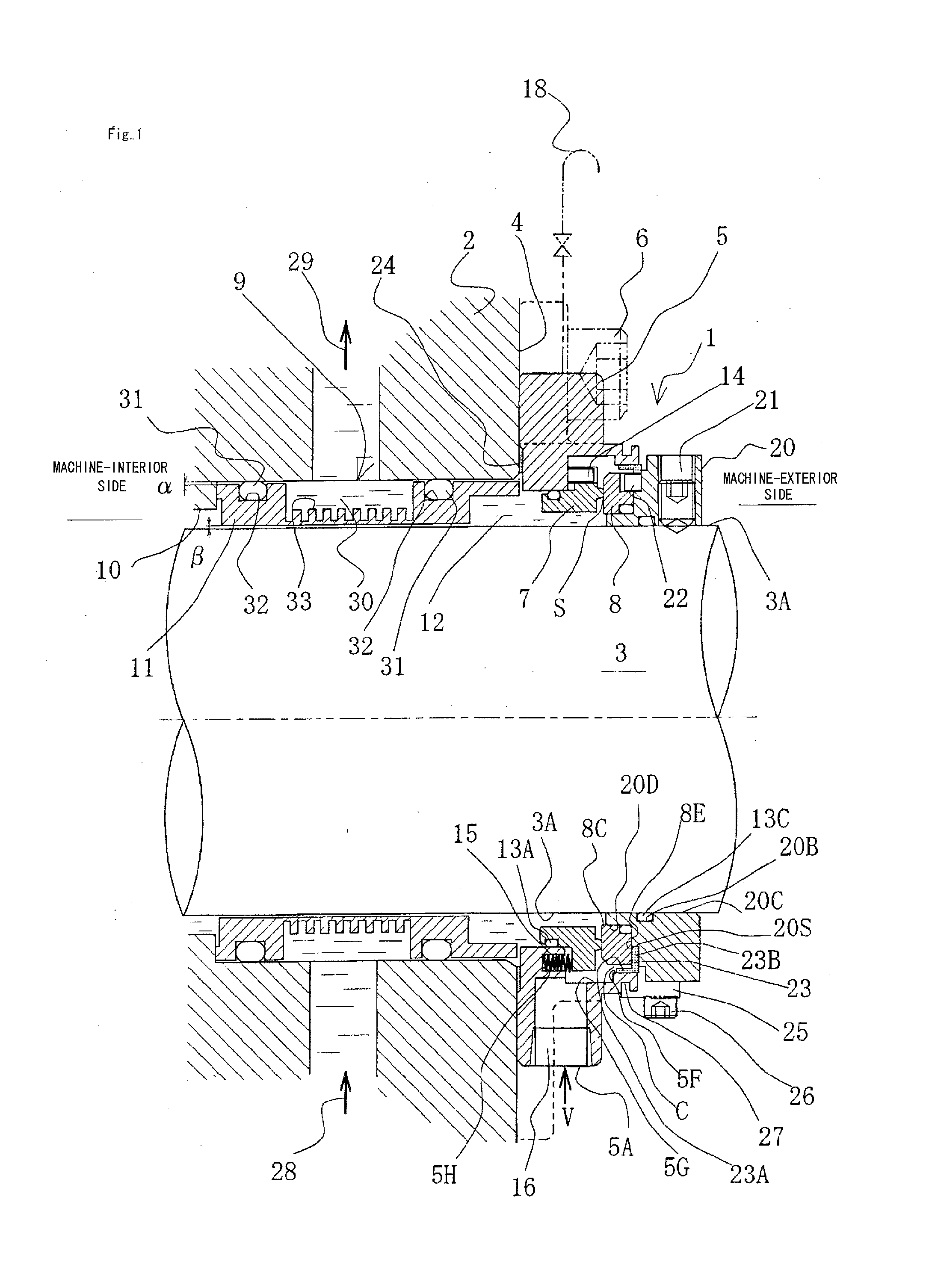
[0030](1) The mechanical seal is of an “outside type” for sealing a sealed fluid that may leak from an inside periphery of a sliding face towards an outside periphery; a rotating-side sealing element and a stationary-side sealing element are disposed so as to be situated externally with respect to a
stuffing box; the stationary-side sealing element, which accommodates a spring, is installed on a seal cover that is secured to the housing; the rotating-side sealing element is installed on a collar that is installed directly on the rotating shaft; the rotating side, which comprises the rotating-side sealing element and the collar, is positioned such that rotation takes place in the
atmosphere on a
machine-exterior side; a balance ratio A2 / A1 is 1 or less, A1 being an axial-direction projection area of the sliding face of the stationary-side sealing element and A2 being an axial-direction projection area that is subjected to a seal
fluid pressure acting as a motive force in the axial direction relative to the stationary-side sealing element; and an annular cooling jacket is disposed between an inside periphery of the housing and an outside periphery of the rotating shaft. Such a configuration affords a no-flushing and no-cooler design despite the sealed fluid being a high temperature fluid. In addition, since there is no need for flushing lines, a cooler, a
coolant line for the cooler, and the like, not only is the
initial cost lower for the mechanical seal, the
initial cost can be appreciably reduced as a result of the more compact size. Concomitantly, it is possible to avoid reduced
thermal efficiency of the
system as a whole due to cooled liquid entering the pipeline
system. Moreover,
coolant for the cooler is unnecessary, affording appreciable reductions in water usage while at the same time eliminating the need for maintenance of the cooler and flushing system. Additionally, there is no need for a pumping ring or ancillary components, and the
stuffing box can be shorter, while the absence of any need to operate a pumping ring significantly reduces running costs as well. Further, heat of sliding is easily radiated away, and the rotating side undergoes
forced air cooling with outside air. Additionally, the seal size may be reduced by the equivalent of the sleeve thickness, whereby
peripheral speed at the sliding face is lower, and the load on the sliding face is lower.
[0031](2) A coolant-accommodating space that communicates with coolant feed and
discharge openings provided to the stuffing box is present in a
central region of the cooling jacket, and the cooling jacket is hermetically installed along the inside periphery of the housing with O-rings interposed at the outside periphery on both ends; and the gap between the outside periphery of the cooling jacket and the inside periphery of the housing is made larger than the gap between the outside periphery of the rotating shaft and the inside periphery of the cooling jacket. According to such a configuration, the gap between the outside periphery of the rotating shaft and the inside periphery of the cooling jacket may be constricted to an extremely small size and the intervening seal fluid present in this gap may be kept to an extremely small volume, so that the
cooling effect of the cooling jacket is maximized. Moreover, in the unlikely event of the rotating shaft wobbling and the outside periphery of the rotating shaft contacting the inside periphery of the cooling jacket, the fact that the
impact is absorbed by the
cushioning action provided by the elasticity of the O rings allows the contact
surface pressure to be kept to a minimum,
grinding or wear of the two components due to contact sliding to be prevented, the initial gap to be maintained, and the
cooling effect produced by the cooling jacket to be maximized for a prolonged period of time.
[0032](3) A plurality of fins are disposed within the coolant-accommodating space towards the outside periphery of the rotating shaft, whereby the
heat transmission area can be larger, and the
axial length of the cooling jacket can be smaller.
[0033](4) The seal cover is provided with a
quenching opening for supplying air or an
inert gas such as
nitrogen gas to a
machine-exterior side of the sliding portions of the rotating-side sealing element and the stationary-side sealing element, whereby the sliding faces can be cooled directly, and
cooling effect can be enhanced.
[0034](5) A
lip seal made of a fluororesin is installed between the rotating-side sealing element and the collar, and the seal portion of the
lip seal is caused to slide in contact with a restriction surface of the inside periphery of the seal cover. According to such a configuration, any
hazard posed by scattering of leaked fluid can be prevented, and leaked fluid does not scatter towards the bearing box, thus preventing damage to the bearing.

