Optical probe having a position measuring system

a position measuring system and optical probe technology, applied in the field of optical probes, can solve the problems of inability to know for certain that a biopsy is taken from the correct part of the tissue, the guidance method is far from optimal, and the resolution is limited, so as to reduce the need for precision, reduce the unit-price per probe, and minimize the contribution to the displacement of the optical guide

Active Publication Date: 2011-08-18
KONINKLIJKE PHILIPS ELECTRONICS NV
View PDF15 Cites 14 Cited by
  • Summary
  • Abstract
  • Description
  • Claims
  • Application Information

AI Technical Summary

Benefits of technology

[0011]In that way, by measuring the induced voltage change resulting in when said internal arrangement changes a direct feedback signal is provided indicating the precise position of the lens system. Such an optical probe is particularly suited for miniature applications e.g. for in-vivo medical application. It should further be mentioned that the optical probe according to the present invention is particularly suited for relative simple and large-scale manufacturing because of the lens system being displaceably mounted on the end portion optical guide. From a practical point of view, this may reduce the needed precision during manufacturing which, in turn, may lower the unit-price per probe. This is especially important because an endoscope, a catheter or needle with the optical probe embedded will normally be disposed after a single use due to sanitary requirements.
[0012]In one embodiment, the sensing current is a high frequency alternating current (AC), the frequency of the AC being selected such that its contribution to the displacement of the optical guide is minimized.

Problems solved by technology

Although helpful, these methods of guidance are far from optimal.
The resolution is limited and, furthermore, these imaging modalities can in most cases not discriminate between benign and malignant tissue.
As a result one does not know for certain that from the correct part of the tissue a biopsy is taken.
Accordingly, since these biopsies are performed without direct feedback this procedure is prone to errors.

Method used


Image

  • Optical probe having a position measuring system
  • Optical probe having a position measuring system
  • Optical probe having a position measuring system

Examples


Embodiment Construction

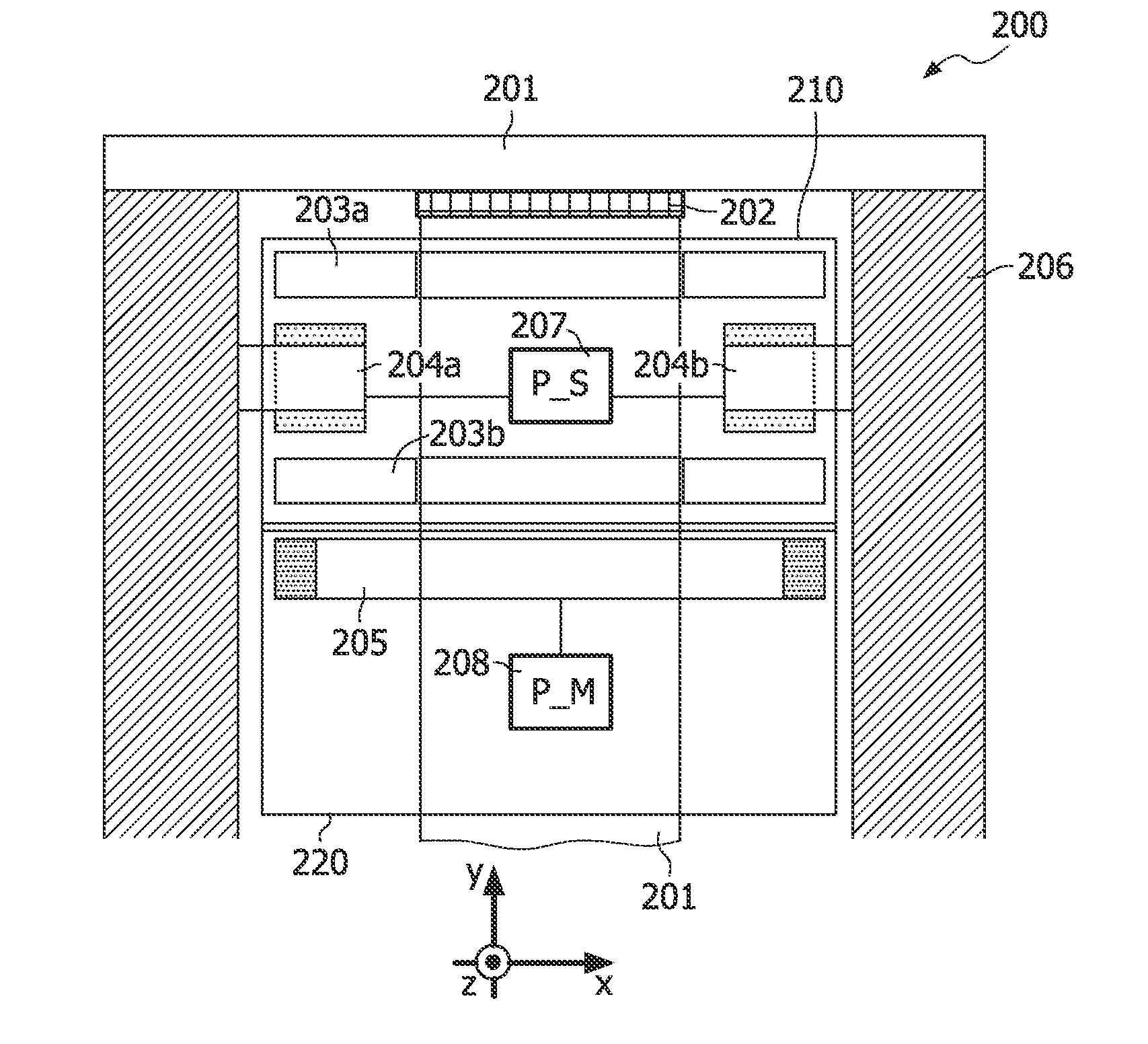
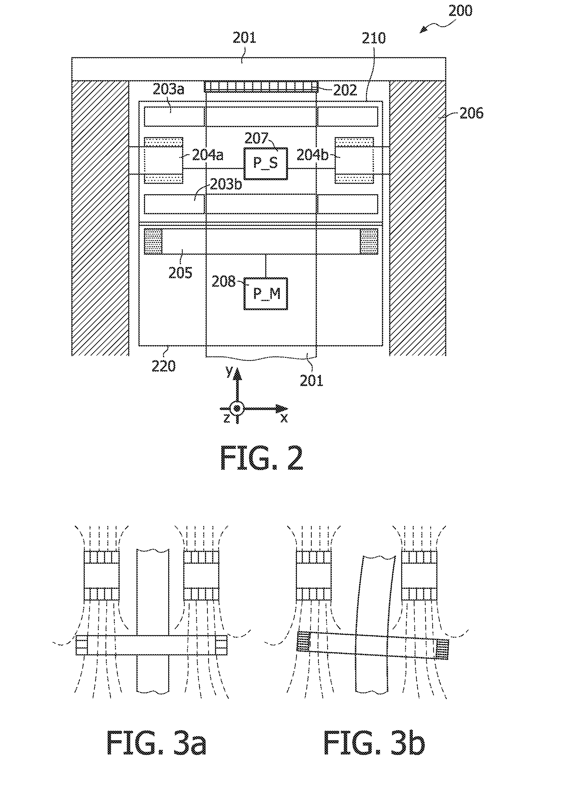
[0043]FIG. 2 shows an optical probe 200 according to the present invention, comprising an optical guide 201, an actuating means 210 and a position measuring system 220.

[0044]Typically, the optical guide 201 is made of a flexible material so as to facilitate inspection on not easy accessible positions, e.g. in-vivo medical inspection and / or sample taking. Various solutions for displacement of an optical guide 2 at an end of a probe are discussed in US2001 / 0055462, which is hereby incorporated by reference in its entirety.

[0045]In the context of the present invention it is to be understood that the term “optical guide” may include, and is not limited to, optical fibres (multi-mode and single-mode), thin film optical paths, photonic crystal fibres, photonic bandgab fibres (PBG), polarization maintaining fibres, and the like. The optical probe may also comprise more than one fibre i.e. a plurality of fibres or a fibre bundle.

[0046]In one embodiment, the optical probe 200 further compris...


PUM


Abstract

This invention relates to an optical probe (200) and an optical imaging system, including an optical guide (201) having a proximal end and a distal end, an actuation means having driving coils (204) and a magnet, with of which being attached to the optical guide. By supplying a driving current through the driving coils a magnetic flux is generated which interacts with the magnet forming a driving force acting at on the optical guide causing a displacement of the distal end of the optical guide. A position measuring including a position measuring coil (205) is used for monitoring the position of the optical guide, where the internal arrangement of the position measuring coil and the driving coils is such that said displacement of the distal end of the optical guide causes a change in the internal arrangement. A power supply supplies an additional high frequency alternating current (AC) through the driving coils which causes an induced voltage in the position measuring coil and thus generates a magnetic coupling between the position measuring coil and the driving coils. A position measuring means measures the displacement of the distal end of the optical guide by means of measuring the induced voltage resulting in when the internal arrangement changes. This induced voltage change being indicative for the position of the distal end.

Description

FIELD OF THE INVENTION[0001]The present invention relates to an optical probe suitable for miniature applications, e.g. in-vivo medical inspections and procedures or in industrial inspections, for instance inspection of food or small devices. The invention also relates to a corresponding imaging system and a method for imaging with such an imaging system.BACKGROUND OF THE INVENTION[0002]For correct diagnosis of various cancer diseases biopsies are taken. This can either be via a lumen of an endoscope or via needle biopsies. An example of a needle biopsy is shown in FIG. 1, where a biopsy is taken from the prostate via the rectum. In order to find the correct position to take the biopsy, various imaging modalities are used such as X-ray, MRI and ultrasound. In case of prostate cancer in most cases the biopsy is guided by ultrasound. Although helpful, these methods of guidance are far from optimal. The resolution is limited and, furthermore, these imaging modalities can in most cases ...

Claims


Application Information

Patent Timeline
Patent Type & Authority Applications(United States)
IPC IPC(8): A61B5/05
CPCA61B1/00096A61B1/00163A61B1/00165A61B1/00188A61B5/0062A61B2019/5251A61B5/061A61B5/062A61B5/065A61B19/5212A61B2019/2253A61B5/0084A61B34/73A61B90/361A61B2034/2051
Inventor HEZEMANS, CORNELIS A.HENDRIKS, BERNARDUS H.W.BIERHOFF, WALTHERUS C.J.BRAUN, AUGUSTINUS L.DESJARDINS, ADRIEN E.
Owner KONINKLIJKE PHILIPS ELECTRONICS NV
Why Eureka
Try Eureka