Tangential combustor with vaneless turbine for use on gas turbine engines

a combustor and vaneless technology, which is applied in the direction of machines/engines, efficient propulsion technologies, light and heating apparatus, etc., can solve the problems of reducing the life of components, reducing the cost of manufacturing, and reducing the size of the required section, so as to reduce the length of the corrugation section, reduce the cost of manufacturing, and reduce the required size

Active Publication Date: 2011-09-01
TOQAN MAJED +3
View PDF23 Cites 34 Cited by
  • Summary
  • Abstract
  • Description
  • Claims
  • Application Information

AI Technical Summary

Benefits of technology

[0008]With regard to the present invention, there is provided a novel and improved combustor design that is capable of operating in a typical fashion, but displaces the need for a vane nozzle by the combination of having the flue gas exit the combustor with a tangential angle and using the proposed corrugated combustor geometry. The invention consists of a modified combustor liner with corrugations that protrude into and across the entire hot gas stream and also twist about and along the engine centerline. The corrugations turn and accelerate the hot gases to the ideal velocity for the turbine inlet as a typical gas turbine vane nozzle would. To decrease the length of the corrugation section, the fuel/air nozzles are setup in a circumferential mode around the combustor liners in order to establish the tangential angle at the combustor exit. As with other engine components, the corrugations cannot escape the volatile environment in the hot gas path; therefore, impingement, effusion or any other cooling method can be utilized. Cooling air is supplied via the compressor discharge air, which flows between the main combustor liner and another encompassing it and travels through the inside of the corrugations (outside the liner containing the combustion), where it cools the combustor material, and then mixes with the hot gases just upstream from the turbine or the heated air is directed to enter the combustion chamber through the fuel/air nozzles. This invention will result in the removal of the nozzle guide van

Problems solved by technology

These hostile conditions cause thermal oxidation and surface deterioration leading to reduced component life.
A variety of designs, materials and configurations are used in gas turbine engines that provide structural robustness as well as effectively cool the turbine vanes and blades in order to enhance its durability ag

Method used


Image

  • Tangential combustor with vaneless turbine for use on gas turbine engines
  • Tangential combustor with vaneless turbine for use on gas turbine engines
  • Tangential combustor with vaneless turbine for use on gas turbine engines

Examples


Embodiment Construction

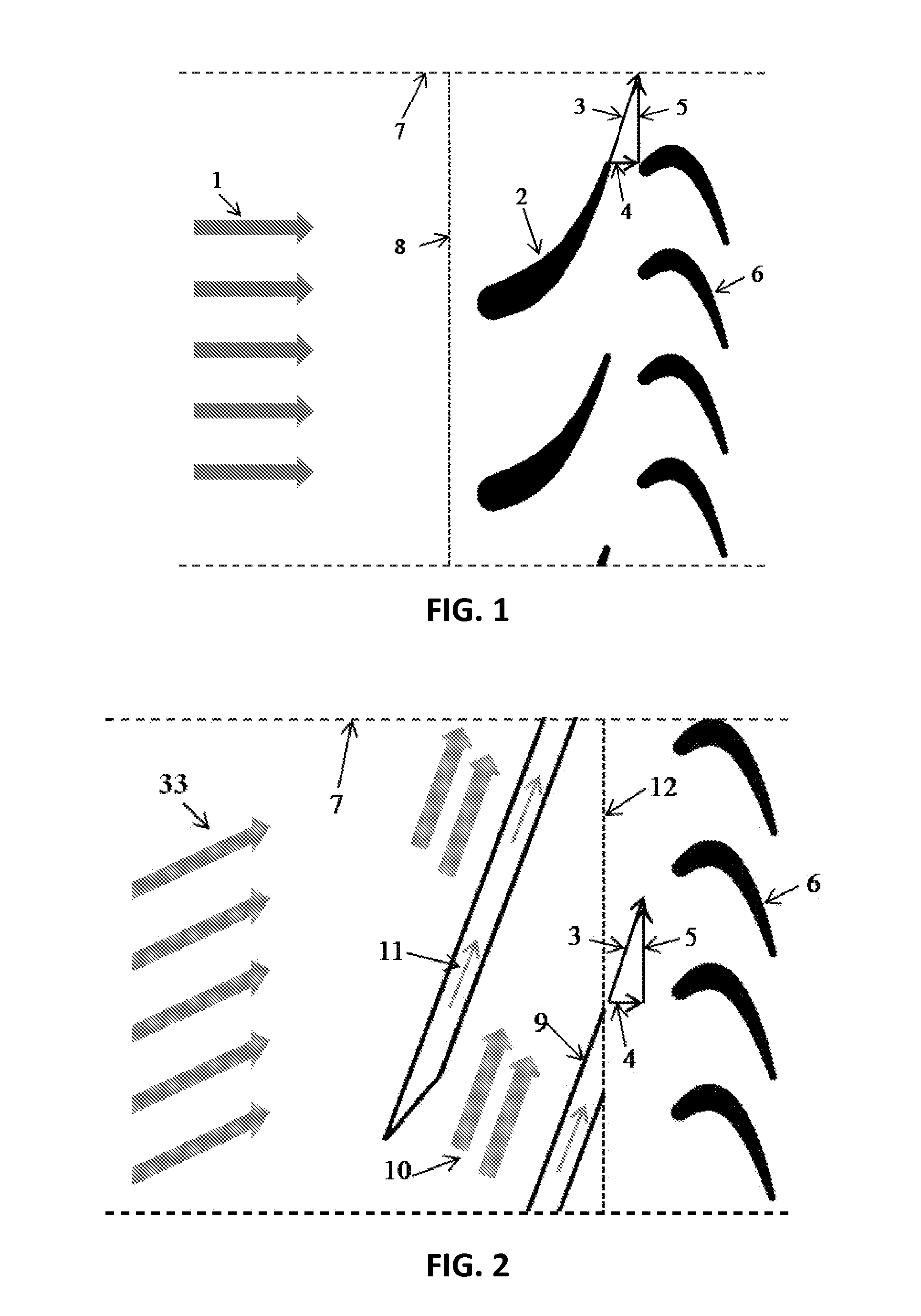
[0027]FIG. 1 shows the general premise of the combustor and first stage turbine of a gas turbine engine. Hot, combusted gases 1 flow in the longitudinal direction where they exit the combustor threshold 8. From there, the gases are accelerated and guided by the first stage vane 2 from which the gases now have a resultant velocity 3 with a longitudinal component 4 and a circumferential component 5 and minimal radial component. This accelerated and turned gas flow then flows around the first stage turbine blades 6, where work is extracted and transferred to the turbine blades and the rotor connected thereto.

[0028]FIG. 2 shows the general premise of the invention and consists of the modified combustor and first stage turbine blades, which are to work on a gas turbine engine. Here, hot combusted gases that have a substantial circumferential component of velocity 33 from the tangentially aimed fuel air nozzles, flow through the combustor where it is further turned and accelerated through...


PUM


Abstract

A combustion device used in gas turbine engines includes an annular combustor that contains the combustion process of air and fuel and then guides the hot gas products to a first stage turbine subsection of a gas turbine engine. The annular combustor has an inner/outer shell having corrugated surfaces that extend radially outward and inward across an entire hot gas stream inside the annular combustor. The corrugations twist about the engine centerline in a longitudinal direction of travel of the engine. The resulting flow path accelerates and turns the hot gas stream to conditions suitable for introduction into the first stage turbine blades, which eliminate the need for first stage turbine vanes. The annular combustor is configured with a system of fuel and air inlet passages and nozzles that results in a staged combustion of premixed fuel and air.

Description

CROSS-REFERENCE TO RELATED APPLICATION[0001]This application claims the benefit of U.S. Provisional Patent Application Ser. No. 61 / 180,909, filed May 25, 2009.FIELD OF THE INVENTION[0002]This invention relates to devices in gas turbine engines that contain the combustion of a fuel and air flow as well as devices that manipulate the hot gases' trajectory in such a way to take an ideal path entering the turbine stage. Such devices include but are not limited to fuel-air nozzles, combustor liners and casings, flow transition pieces, and guide vanes that are used in military and commercial aircraft, power generation, and other gas turbine related applications.BACKGROUND OF THE INVENTION[0003]Gas turbine engines include machinery that extracts work from combustion gases flowing at high temperatures, pressures and velocity. The extracted work can be used to drive a generator for power generation or for providing the required thrust for an aircraft. A typical gas turbine engine consists of...

Claims


Application Information

Patent Timeline
IPC IPC(8): F23R3/42F02C3/14
CPCF01D9/023Y02T50/675Y02T50/67F23R3/52F23R3/002F23R3/007F23R3/16Y02T50/60F23R3/06
Inventor TOQAN, MAJEDGREGORY, BRENT ALLANYAMANE, RYAN SADAOREGELE, JONATHAN DAVID
Owner TOQAN MAJED
Why Eureka
Try Eureka