
Underwater sensor apparatus

a sensor and underwater technology, applied in the field of underwater sensor apparatus, can solve the problems of other known apparatus, inability to guarantee vessel availability, and high cost of operating a manned vessel on the high seas, and achieve the effects of high resolution data, easy connection to fishing lines, and small siz

Active Publication Date: 2011-09-08
YSI INC
View PDF13 Cites 47 Cited by
  • Summary
  • Abstract
  • Description
  • Claims
  • Application Information

AI Technical Summary

Benefits of technology

It is another object of embodiments of the disclosure to provide an underwater sensor apparatus having weighting for directional stability and control.
It is an object of embodiments of the disclosure to provide an underwater sensor apparatus having a small size such that the apparatus can be held in the user's hand, can fit in the user's pocket or be easily tied to a fishing line.
It is another object of embodiments of the disclosure to provide an underwater sensor apparatus having sensors with rapid response capability so the apparatus can collect high resolution data while being rapidly submerged.
It is an object of embodiments of the disclosure to provide an underwater sensor apparatus having sensors located within a channel to protect the sensors from damage.
It is another object of embodiments of the disclosure to provide an underwater sensor apparatus having a channel and sensors located within the channel to eliminate the need for a pumping system to facilitate water flow on the sensors.
It is another object of embodiments of the disclosure to provide an underwater sensor apparatus that is easily castable.

Problems solved by technology

The cost of operating a manned vessel on the high seas often is prohibitive.
Moreover, vessel availability cannot always be assured.
However, these and other known apparatus have many disadvantages.
Another common disadvantage is a delay in seeing the collected data because downloading and processing data can be complicated and time consuming.
Many existing underwater sensor apparatus are cumbersome to handle and deploy and may require a special winch for handling.

Method used


Image

  • Underwater sensor apparatus
  • Underwater sensor apparatus
  • Underwater sensor apparatus

Examples


Embodiment Construction

In the following paragraphs, embodiments of the disclosure will be described in detail by way of example with reference to the attached drawings. Throughout this description, the exemplary embodiments and examples shown should be considered as exemplars, rather than as limitations on embodiments of the disclosure. As used herein, the “embodiments,”“exemplary embodiments” or “embodiments of the disclosure” refer to any one of the embodiments described herein, and any equivalents. Furthermore, reference to various feature(s) of the “embodiments,”“exemplary embodiments or “embodiments of the disclosure” throughout this document does not mean that all claimed embodiments or methods must include the referenced feature(s).

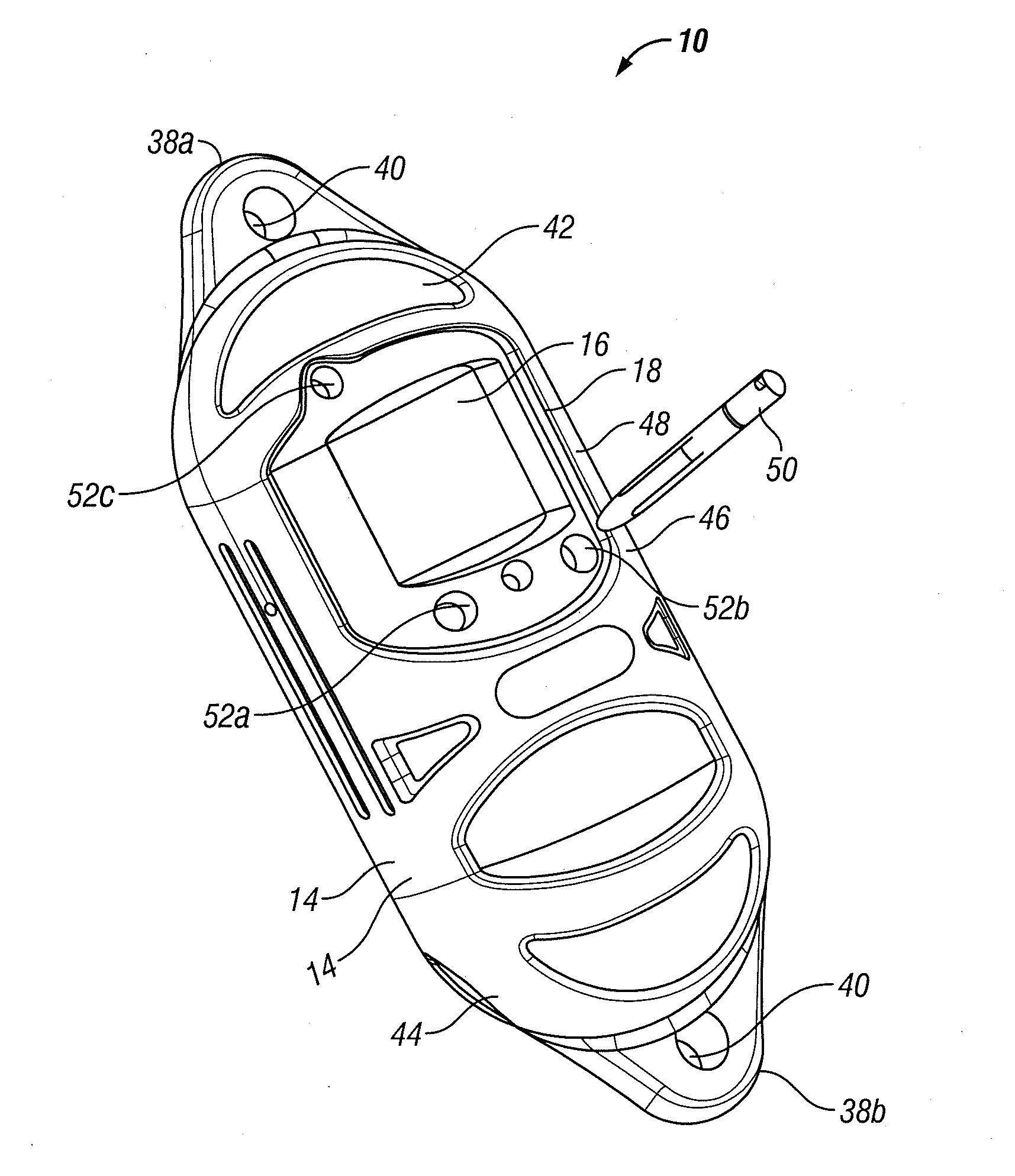
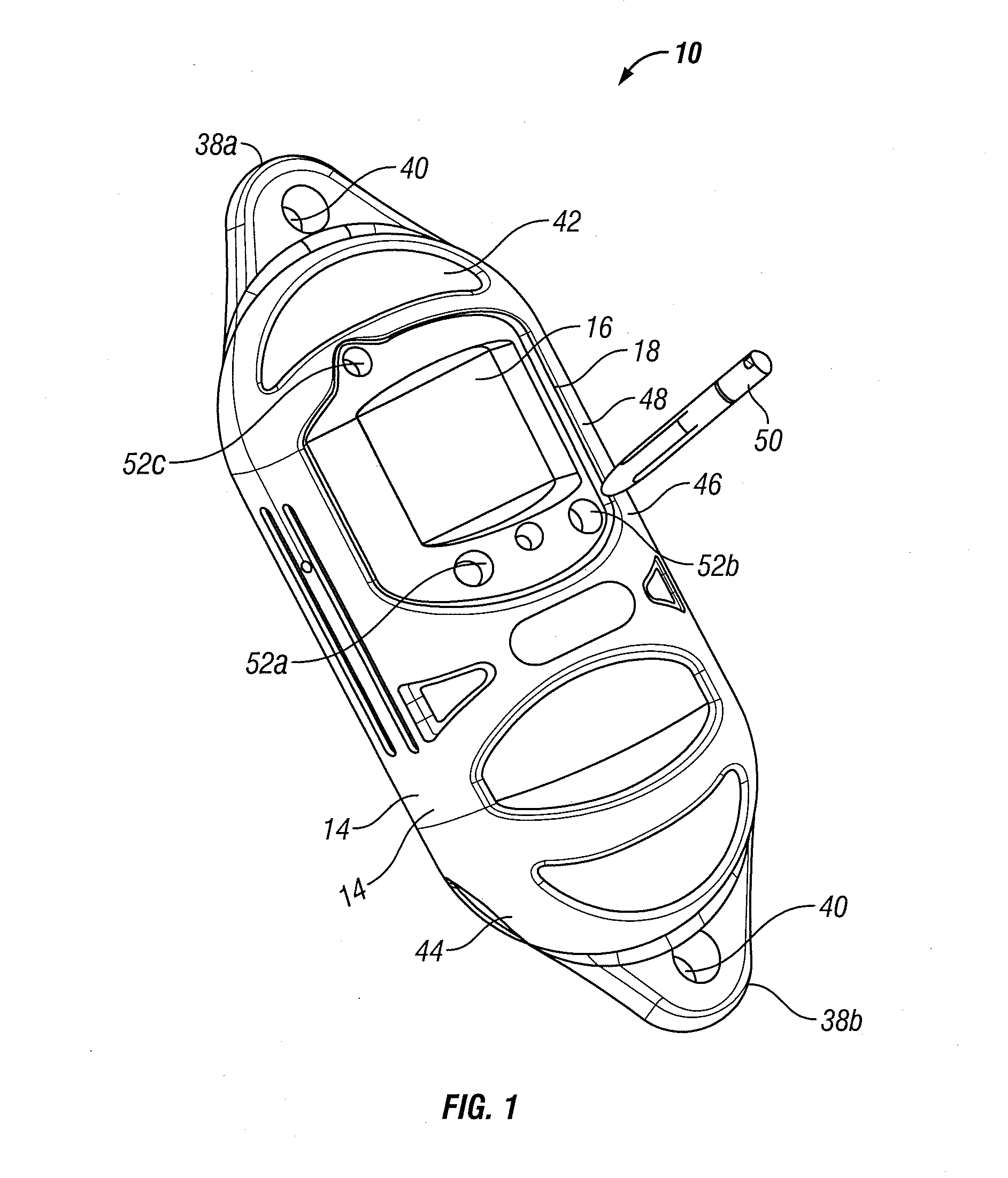
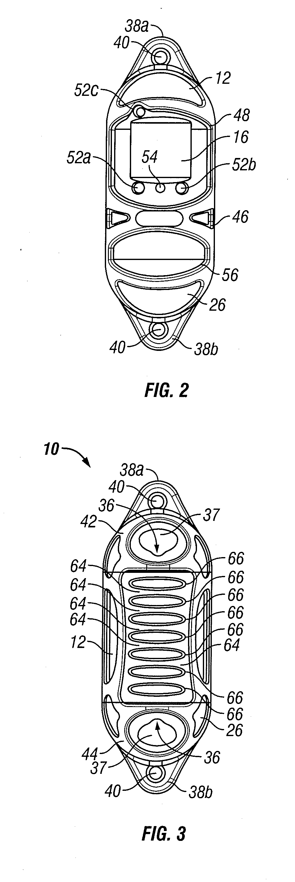
Referring first to FIGS. 1-8, exemplary embodiments of an underwater sensor apparatus will be described. Underwater sensor apparatus 10 comprises two housing components 12a, 12b and jacket 14. A first housing component 12a houses the display 16 and includes window 22 to ...


PUM


Abstract

An underwater sensor device comprises a submersible housing including one or more housing components, one or more sensors for monitoring and collecting water characteristics, a controller for controlling operations of the one or more sensors and an graphical user interface mounted to the housing that displays the water environmental data. The housing defines a channel that extends through one of the housing components, and at least one of the sensors is mounted to the housing and extends into the channel. The controller is disposed within the housing and is operatively connected to the one or more sensors.

Description

BACKGROUNDThere are numerous indicia of water phenomena that are of value to oceanographers, hydrologists and surveyors as well as to the captain and crew of surface or subsurface vessels. For example, water temperature, depth, conductivity, salinity, sound speed, optical properties, nutrient availability, etc., may provide valuable information for a number of divergent uses. This information may be used to expand the knowledge base of ocean parameters in general, or may be useful in navigation, sonar communication and the like.Historically, data collection has been completed using instruments lowered from ships, or moored instrument arrays which must be recovered. The cost of operating a manned vessel on the high seas often is prohibitive. Moreover, vessel availability cannot always be assured. Oceanographic experiments are thus constrained in many cases by factors other than the phenomenon which is intended for study.There are numerous apparatus available to measure various ocean ...

Claims


Application Information

Patent Timeline
IPC IPC(8): G01C13/00
CPCG01N33/1886G01C13/00G01D11/245G01N2001/021
Inventor CABRERA, RAMONGROZEV, ZHIVKOKOVACHEV, ALEXANDERSLOCUM, DARYL B.JACKSON, ADAMOSIECKI, DANIEL
Owner YSI INC
Learn More